

Liquid treating device
A liquid treatment and liquid technology, applied in the field of liquid treatment devices, can solve the problems of low plasma 805 generation efficiency, liquid 803 sterilization requiring a long time, high applied voltage, etc. improved effect
- Summary
- Abstract
- Description
- Claims
- Application Information
AI Technical Summary
Problems solved by technology
Method used
Image

Examples
Embodiment approach 1
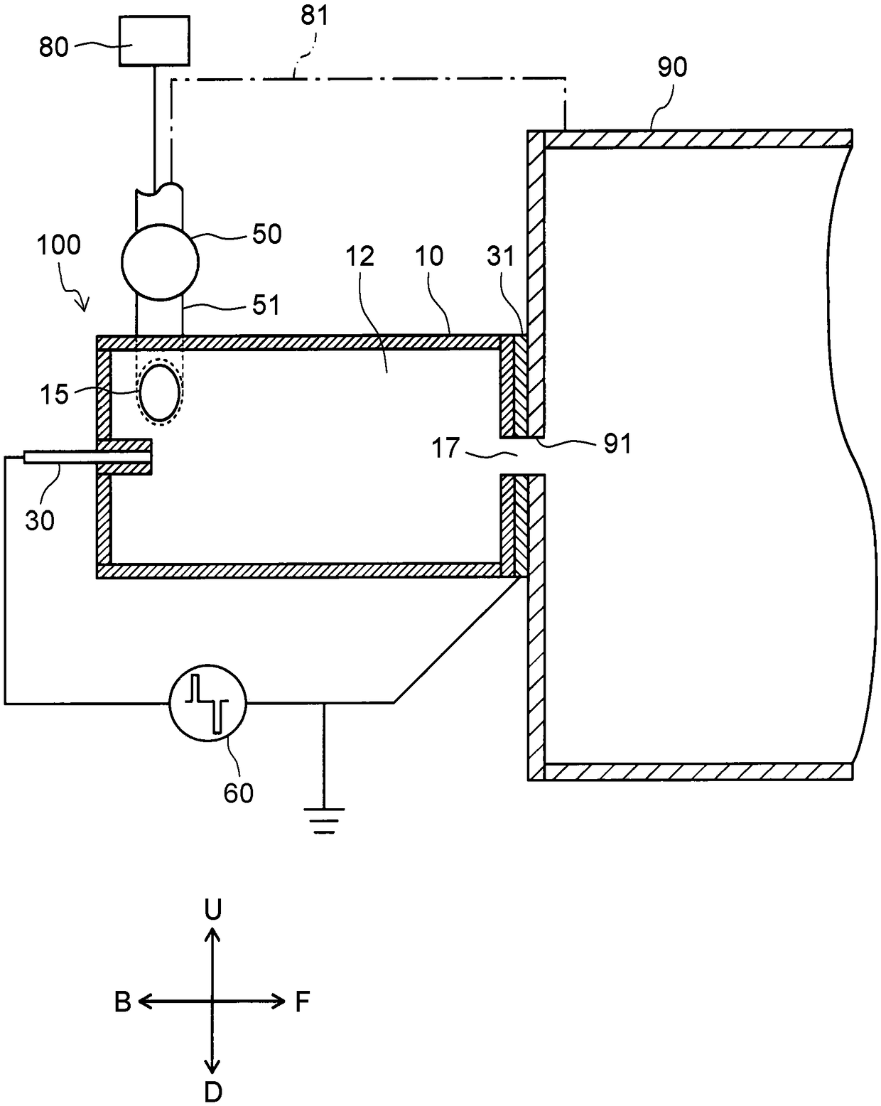
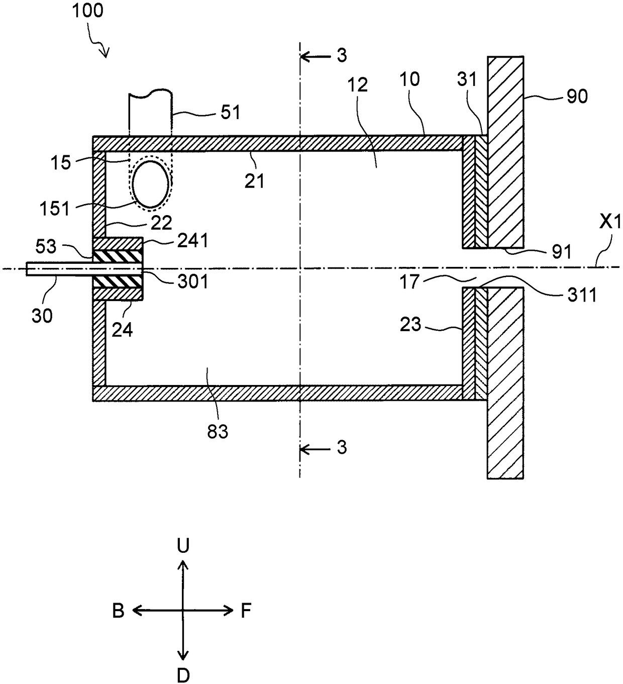
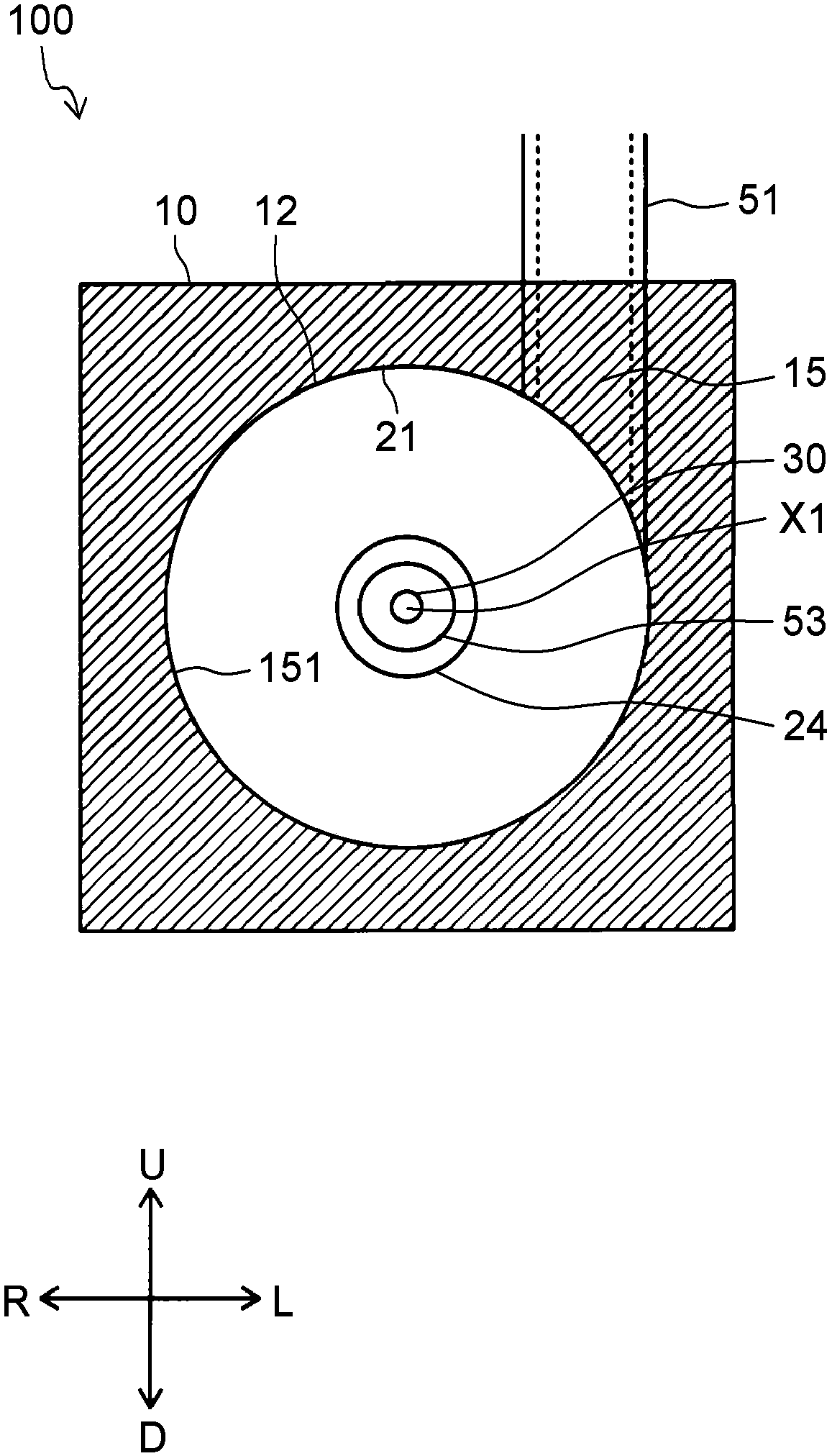
[0036] Hereinafter, the liquid processing device 101 including the liquid processing unit 100 according to the embodiment of the present disclosure will be described in detail with reference to the drawings. In the drawings, the same symbols are assigned to the same or corresponding parts, and description thereof will not be repeated. In addition, in the drawings referred to below, the structures are simplified or schematically shown, or some constituent members are omitted for easy understanding of the description. In addition, the dimensional ratio between the constituent members shown in each figure always represents an actual dimensional ratio.
[0037] [the whole frame]
[0038] The liquid treatment device 101 includes at least a liquid treatment unit 100 having a microbubble generating unit 90, and a treated tank 41 holding a culture solution 42 for plant cultivation (refer to Figure 6D ). The liquid processing unit 100 functions as a device that performs a steriliza...
Embodiment approach 2
[0078] like Figure 6E As shown, as the liquid processing apparatus 102 of Embodiment 2, the topdressing apparatus 45 is further provided with respect to the liquid processing apparatus 101 of Embodiment 1.
[0079] The topdressing device 45 is arranged between the microbubble generating part 90 and the tank 41 to be treated, and applies topdressing components such as potassium to the treatment liquid L2 supplied to the tank 41 to be treated.
[0080] In this way, if the topdressing device 45 is disposed downstream of the treatment tank 12 and the microbubble generator 90 , the balance of the topdressing component or the plurality of topdressing components applied to the treatment liquid L2 can be prevented from being disrupted by the discharge in the treatment tank 12 . That is, since the discharge is performed on the upstream side of the topdressing device 45, the influence of the discharge on the fertilizer components can be suppressed.
Embodiment approach 3
[0082] like Figure 6F As shown, the liquid processing device 103 according to the third embodiment further includes an electrical characteristic measuring device 46 and a top dressing control unit 47 relative to the liquid processing device 102 according to the second embodiment.
[0083] The electrical characteristic measuring device 46 is arranged between the microbubble generating part 90 and the top dressing device 45 , and measures the pH and electrical conductivity of the treatment liquid L2 supplied from the microbubble generating part 90 . The reason for measuring the pH or electrical conductivity of the treatment liquid L2 by the electrical characteristic measuring device 46 is that the composition changes due to discharge, so the measurement is performed immediately in front of the top dressing device 45, and based on the measurement result, the top dressing control unit 47 performs the measurement. The fertilizer components to be added by the topdressing device 45 ...
PUM
 Abstract
Description
Claims
Application Information