

Plasma sterilization bag applicable to disinfection of medical apparatus and instruments and use method of plasma sterilization bag
A technology of plasma and medical equipment, applied in the field of plasma sterilization bags, can solve the problems of secondary pollution and achieve the effect of stable discharge, low power consumption, and high-efficiency sterilization
- Summary
- Abstract
- Description
- Claims
- Application Information
AI Technical Summary
Problems solved by technology
Method used
Image

Examples
Embodiment Construction
[0035] The present invention will be described in detail below in conjunction with the accompanying drawings and embodiments.
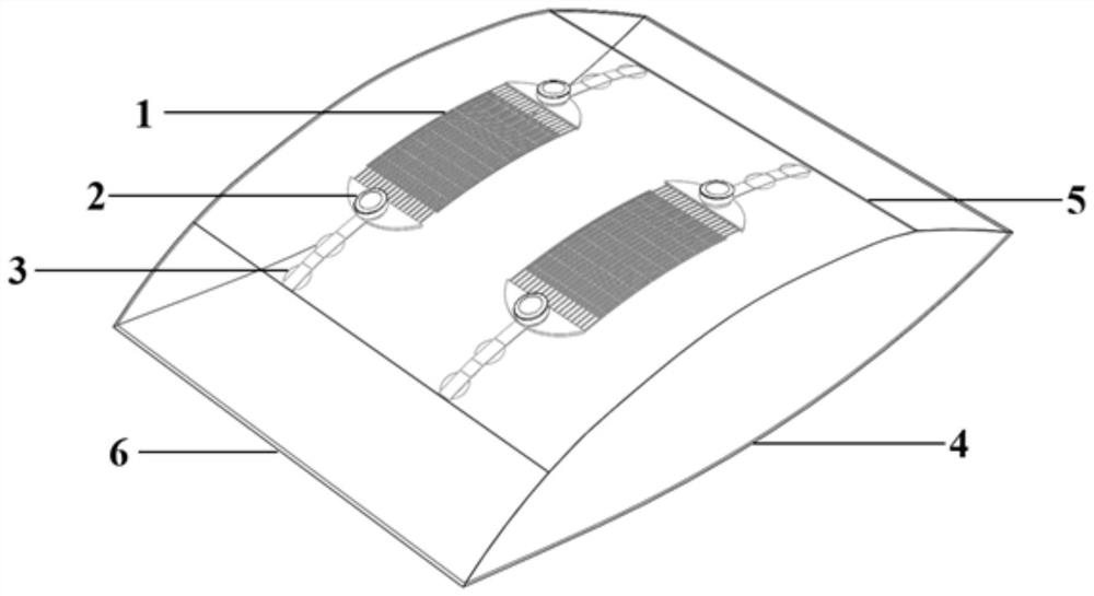
[0036] Such as figure 1 As shown, it includes a sealed bag 4 and at least one flexible electrode 1, and each flexible electrode 1 is fixed on the inside of the sealed bag 4 by two sets of metal snap buttons 3, one end of the metal snap button 3 is fixed on the inner side, and the other end is connected to the flexible electrode 1 , the power interface 2 is connected to the metal snap button 3 through the sealed bag 4 through the copper wire.
[0037] In one embodiment, the sealed bag 4 is made of low density polyethylene.
[0038] In one embodiment, there are two flexible electrodes 1 .
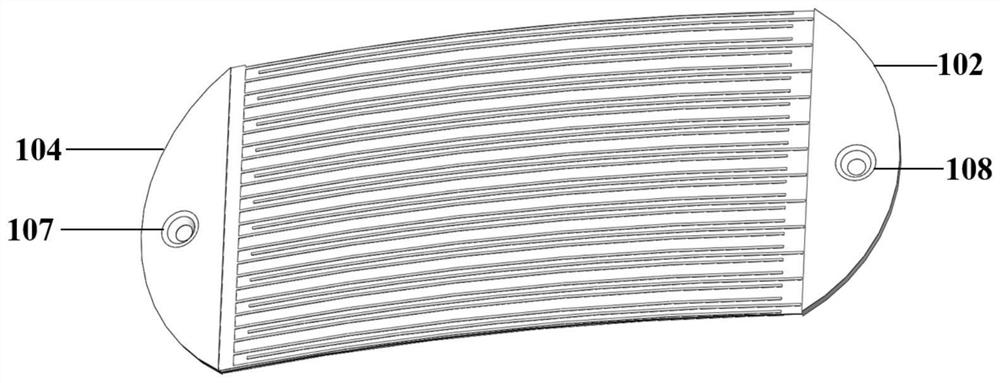
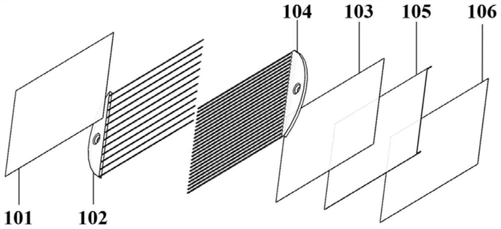
[0039] Such as image 3 As shown, the flexible electrode 1 includes a first insulating medium 101, a first metal electrode 102, a second metal electrode 104, a second insulating medium 103, a copper sheet 105 and a third insulating medium 106 connected in sequence...
PUM
 Abstract
Description
Claims
Application Information