Printing device

a printing device and printing head technology, applied in the direction of printing and inking apparatus, etc., can solve the problems of contamination of the head and its vicinity, and achieve the effect of suppressing the leakage of ink mist, uniform suction flow rate of air, and contamination of the head

Active Publication Date: 2016-02-04
CANON KK
View PDF2 Cites 20 Cited by
  • Summary
  • Abstract
  • Description
  • Claims
  • Application Information

AI Technical Summary

Benefits of technology

[0007]The present invention has been made in view of the circumstance described above. An object of the present invention is to provide an ink jet printing device, which can perform suction substantially at a uniform flow rate across the entire area of the duct opening plane regardless of arrangement of the airflow-forming unit, and reliably suppress contamination of the head and its vicinity by the ink mist.
[0015]According to the present invention, it is possible to achieve a uniform suction flow rate of air at the suction port of the mist collection mechanism, whereby it is possible to suppress leakage of the ink mist and contamination of the head and its vicinity.

Problems solved by technology

This possibly leads to a situation where the air containing the ink mist is not sufficiently collected in such a region, and contaminates the head and its vicinity.

Method used


Image

  • Printing device
  • Printing device
  • Printing device

Examples


first embodiment

[0035]the present invention will be described with reference to FIG. 1A to FIG. 6B.

(Printing Device)

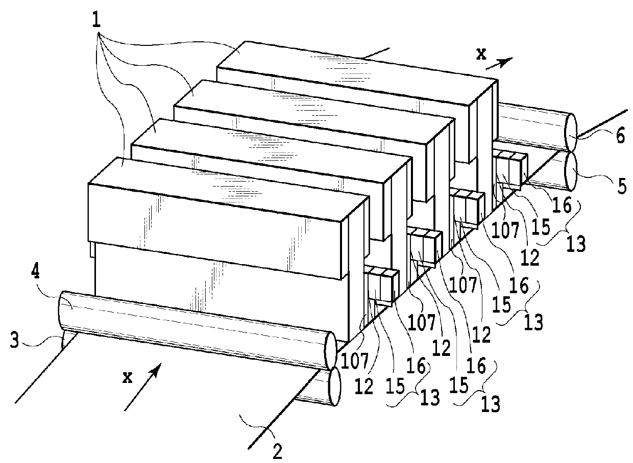
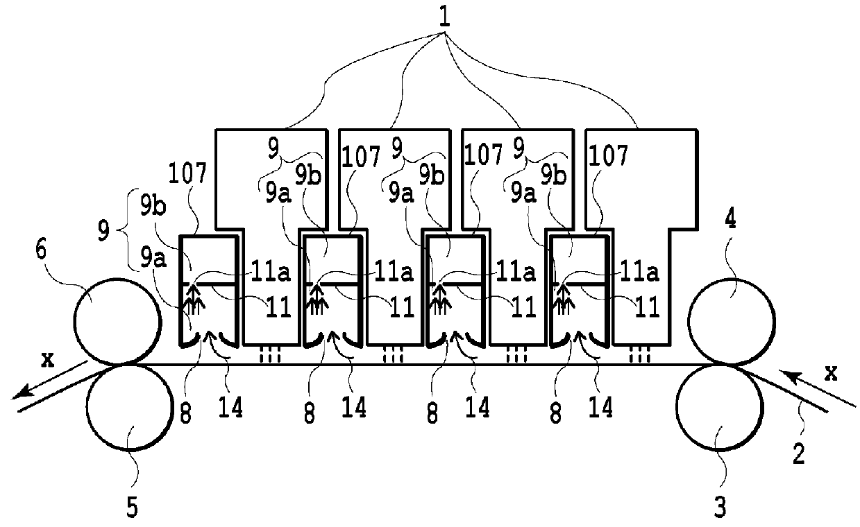
[0036]FIG. 1A is a perspective view schematically illustrating a configuration of the vicinity of a printing unit of an ink jet printing device according to the first embodiment of the present invention. FIG. 1B is a sectional view schematically illustrating the vicinity of the printing unit of the ink jet printing device illustrated in FIG. 1A and taken along a medium conveying direction X.

[0037]The ink jet printing device according to the first embodiment includes a conveying unit having a conveying mechanism that conveys a medium, a printing unit that performs printing on the medium conveyed by the conveying unit, and an ink-mist collection mechanism that collects an ink mist generated from the printing unit.

(Conveying Unit)

[0038]The conveying unit has: a pair of main conveying rollers including a conveying roller 3 and a pinch roller 4 that is driven to rotate by the conveying rol...

second embodiment

[0084]FIG. 7A to FIG. 7C each illustrate a configuration example of a mist collection mechanism according to the present invention. FIG. 7A to FIG. 7C are schematic sectional views along the medium conveying direction X.

[0085]A mist collection mechanism 207 according to the second embodiment includes the spatial region 9b that is disposed in the airflow path 9 and can function as the pressure buffer chamber, whereby it is possible to achieve a uniform flow rate of air on the opening plane of the suction port 8, as described in the first embodiment.

[0086]The mist collection mechanism 207 illustrated in FIG. 7A further includes a blowout port 20 that is disposed on both of the upstream side and the downstream side of the suction port 8 in the medium conveying direction X and blows out air 21 toward the medium 2, and a blowout unit, not illustrated.

[0087]The air 21 blows out from the blowout ports 20 on the upstream side and the downstream side of the suction port 8 in the medium conve...

third embodiment

[0105]The conveying unit, not illustrated, and the printing unit each have a similar configuration to those in the third embodiment, and hence, explanation thereof will not be repeated. However, in this example, in order to achieve a durable printed matter, an ink containing a resin material is used.

(Mist Collection Mechanism)

[0106]The mist collection mechanism 407 according to the fourth embodiment includes, in the airflow path 9, the spatial region 9b that can function as the pressure buffer chamber as described in the first embodiment, which makes it possible to achieve a uniform flow rate of air on the opening plane of the suction port 8. In this embodiment, each of the suction port 8 and the mist collection mechanism 407 has the long side in the printing width direction of the printing device, that is, in the longitudinal direction of the head 301, and has the short side in the medium conveying direction.

[0107]In the third embodiment, the discharging port 321 is provided on bot...


PUM


Abstract

A printing device includes: a head that ejects an ink on a medium to perform printing; and a mist collection mechanism having: a suction port facing the medium and sucking air near the head; an exhaust port discharging the sucked air; and an airflow path between the suction port and the exhaust port, wherein the airflow path includes a first spatial region located on a side of the suction port, and a second spatial region located on a side of the exhaust port and adjacent to the first spatial region through a communicating port having an opening area smaller than that of the suction port.

Description

BACKGROUND OF THE INVENTION[0001]1. Field of the Invention[0002]The present invention relates to a printing device that ejects an ink to perform printing on a medium, in particular, relates to a technique of supplying and discharging air around a print head (hereinafter, also simply referred to as a head).[0003]2. Description of the Related Art[0004]In general, inkjet printing devices have a problem in that minute inks (hereinafter, also referred to as ink mists or simply as mists), which are ejected from an ejection port of a nozzle provided on an ink ejecting surface of the head and do not reach the medium, are blown up by airflow occurring around the head, thereby contaminating the head or the vicinity thereof.[0005]To deal with this, conventionally, there has been used an ink jet printing device configured to suck and collect the ink mists near the head. For example, Japanese Patent Laid-Open No. 2005-271314 discloses a mist collection mechanism, which has a duct extending upwar...

Claims


Application Information

Patent Timeline
Patent Type & Authority Applications(United States)
IPC IPC(8): B41J2/165
CPCB41J2/16535B41J2/16523B41J2/1714B41J2/16538B41J2/16585B41J2202/21
Inventor ISHIDA, KOICHIKUBOTA, MASAHIKOYAMAGUCHI, NOBUHITOARIMIZU, HIROSHIIMAHASHI, YUSUKEMIYAKOSHI, ARIHITOITOH, YOSHINORI
Owner CANON KK
Why Eureka
Try Eureka