Printing device
a printing device and printing head technology, applied in the direction of printing and inking apparatus, etc., can solve the problems of contamination of the head and its vicinity, and achieve the effect of suppressing the leakage of ink mist, uniform suction flow rate of air, and contamination of the head
- Summary
- Abstract
- Description
- Claims
- Application Information
AI Technical Summary
Benefits of technology
Problems solved by technology
Method used
Image
Examples
first embodiment
[0035]the present invention will be described with reference to FIG. 1A to FIG. 6B.
(Printing Device)
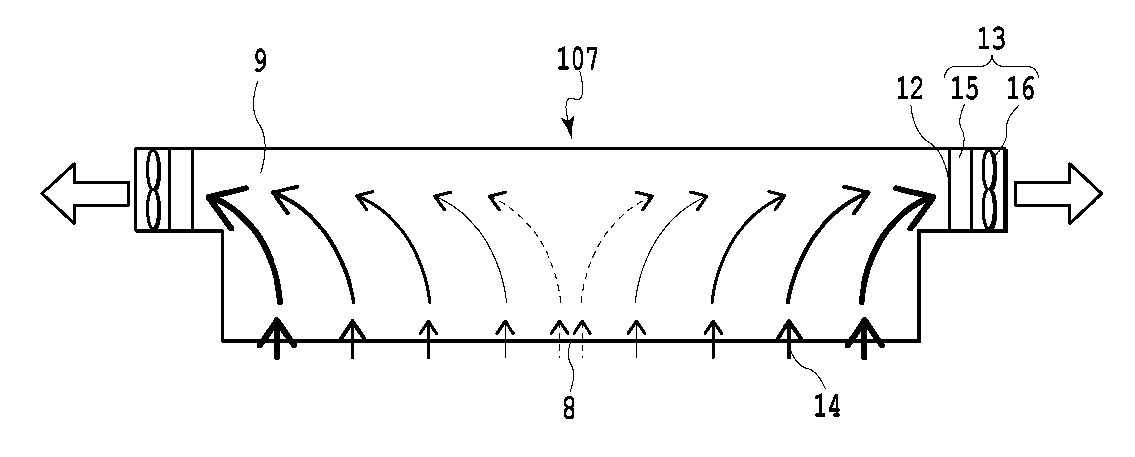
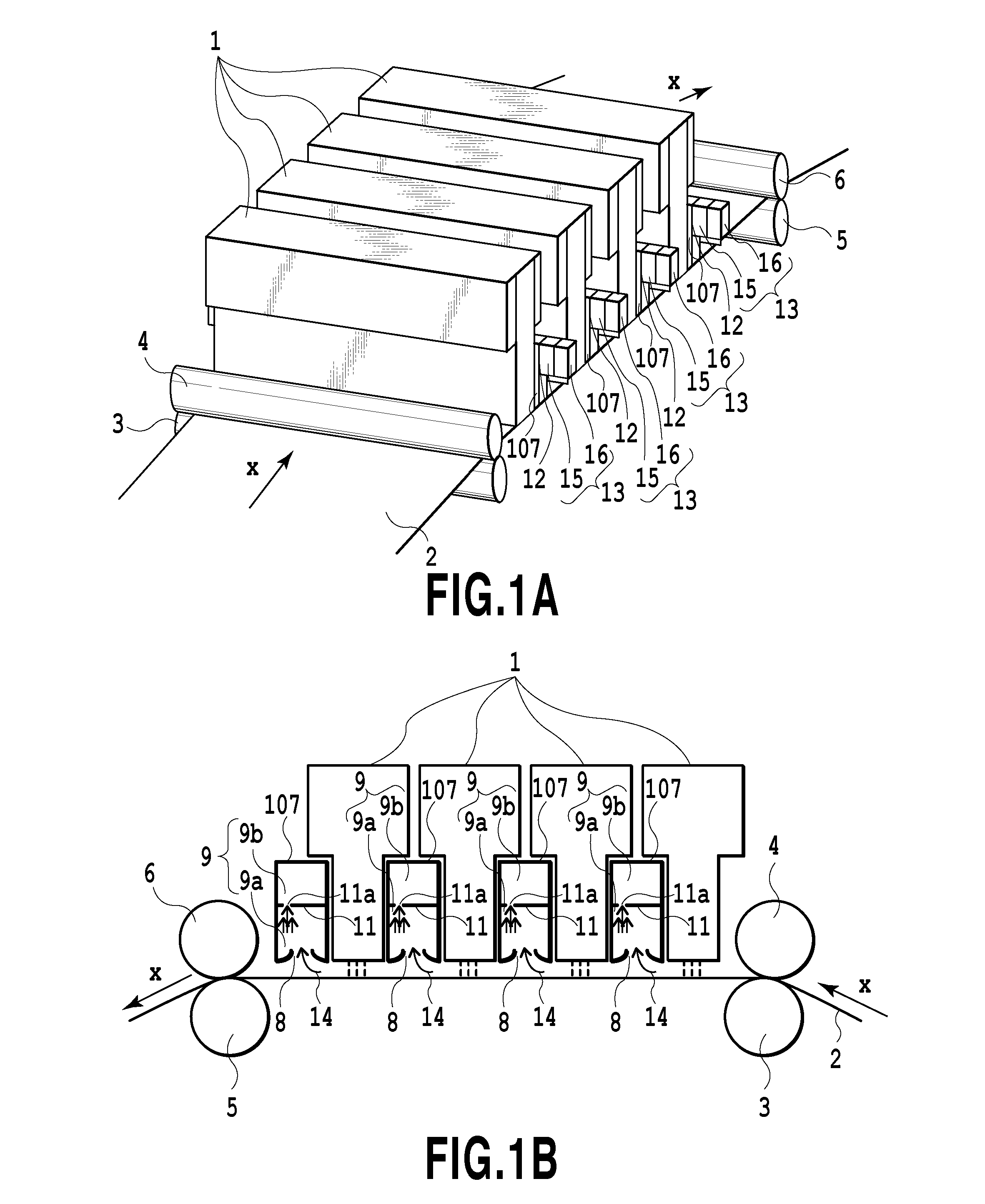
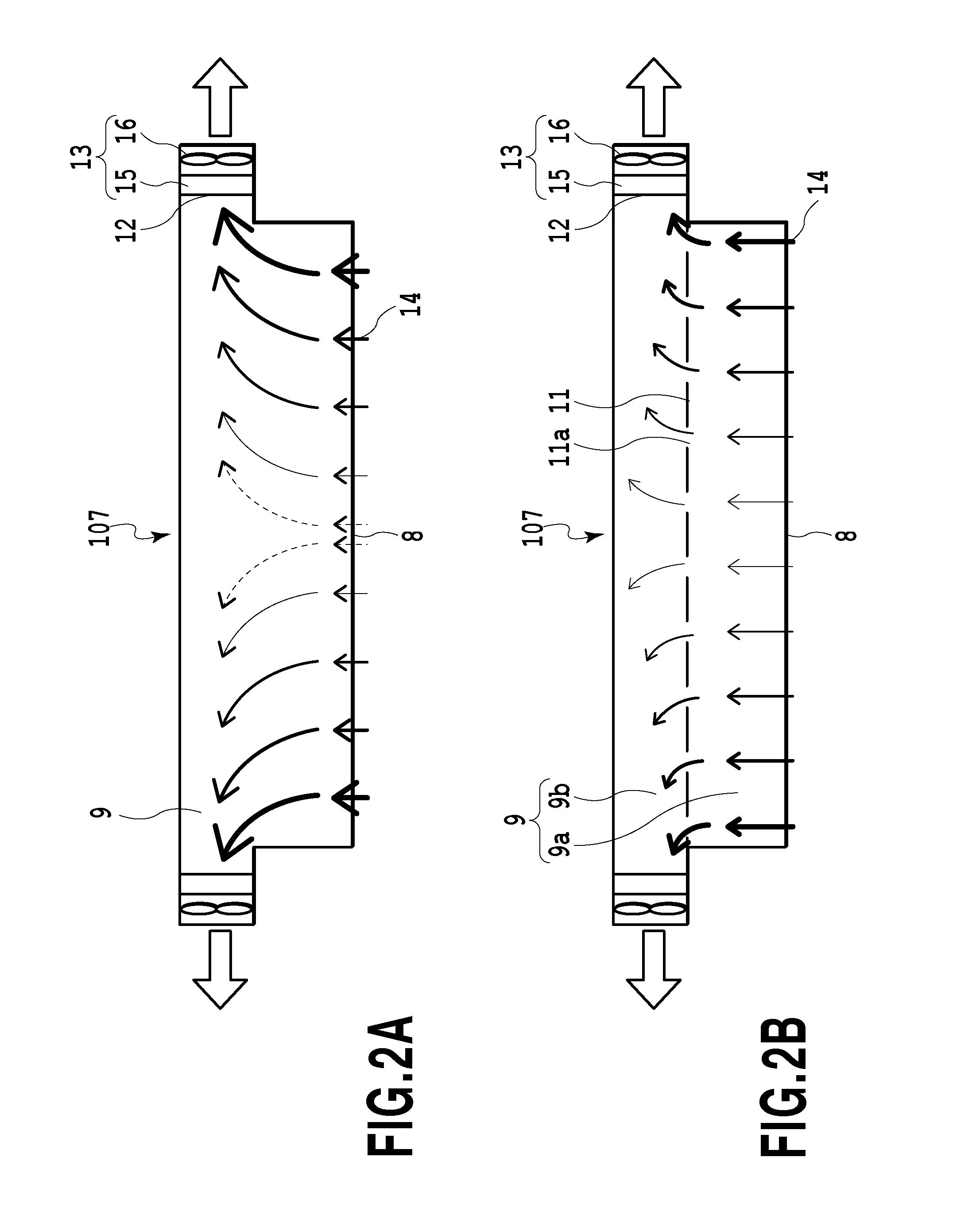
[0036]FIG. 1A is a perspective view schematically illustrating a configuration of the vicinity of a printing unit of an ink jet printing device according to the first embodiment of the present invention. FIG. 1B is a sectional view schematically illustrating the vicinity of the printing unit of the ink jet printing device illustrated in FIG. 1A and taken along a medium conveying direction X.
[0037]The ink jet printing device according to the first embodiment includes a conveying unit having a conveying mechanism that conveys a medium, a printing unit that performs printing on the medium conveyed by the conveying unit, and an ink-mist collection mechanism that collects an ink mist generated from the printing unit.
(Conveying Unit)
[0038]The conveying unit has: a pair of main conveying rollers including a conveying roller 3 and a pinch roller 4 that is driven to rotate by the conveying rol...
second embodiment
[0084]FIG. 7A to FIG. 7C each illustrate a configuration example of a mist collection mechanism according to the present invention. FIG. 7A to FIG. 7C are schematic sectional views along the medium conveying direction X.
[0085]A mist collection mechanism 207 according to the second embodiment includes the spatial region 9b that is disposed in the airflow path 9 and can function as the pressure buffer chamber, whereby it is possible to achieve a uniform flow rate of air on the opening plane of the suction port 8, as described in the first embodiment.
[0086]The mist collection mechanism 207 illustrated in FIG. 7A further includes a blowout port 20 that is disposed on both of the upstream side and the downstream side of the suction port 8 in the medium conveying direction X and blows out air 21 toward the medium 2, and a blowout unit, not illustrated.
[0087]The air 21 blows out from the blowout ports 20 on the upstream side and the downstream side of the suction port 8 in the medium conve...
third embodiment
[0105]The conveying unit, not illustrated, and the printing unit each have a similar configuration to those in the third embodiment, and hence, explanation thereof will not be repeated. However, in this example, in order to achieve a durable printed matter, an ink containing a resin material is used.
(Mist Collection Mechanism)
[0106]The mist collection mechanism 407 according to the fourth embodiment includes, in the airflow path 9, the spatial region 9b that can function as the pressure buffer chamber as described in the first embodiment, which makes it possible to achieve a uniform flow rate of air on the opening plane of the suction port 8. In this embodiment, each of the suction port 8 and the mist collection mechanism 407 has the long side in the printing width direction of the printing device, that is, in the longitudinal direction of the head 301, and has the short side in the medium conveying direction.
[0107]In the third embodiment, the discharging port 321 is provided on bot...
PUM
 Abstract
Description
Claims
Application Information
 - R&D
- Intellectual Property
- Life Sciences
- Materials
- Tech Scout
- Unparalleled Data Quality
- Higher Quality Content
- 60% Fewer Hallucinations
Browse by: Latest US Patents, China's latest patents, Technical Efficacy Thesaurus, Application Domain, Technology Topic, Popular Technical Reports.
© 2025 PatSnap. All rights reserved.Legal|Privacy policy|Modern Slavery Act Transparency Statement|Sitemap|About US| Contact US: help@patsnap.com


