Apparatus for obtaining balanced flow of hot melt in a distribution manifold

a technology of hot melt and distribution manifold, which is applied in the field of distribution manifold, can solve the problems of time-consuming and costly trial-and-error efforts to achieve just the right set of dimensions for the tooling, and complicate the tooling manufacture, so as to achieve the effect of simplifying manufacturing and reducing the degree of constriction

Inactive Publication Date: 2005-08-02
R & D TOOL & ENG
View PDF8 Cites 18 Cited by
  • Summary
  • Abstract
  • Description
  • Claims
  • Application Information

AI Technical Summary

Benefits of technology

[0004]The present invention addresses these problems by providing adjustable restrictor devices in operable association with at least some of the branch passages in a distribution manifold so that the time of delivery of the hot melt into all of the injection cavities in the set can be synchronized and the rate of fill can be rendered essentially uniform across all of cavities of the set. In a preferred embodiment, all of the branch passages can be of the same diameter, and all of the nozzle tips and nozzle passages can likewise be of uniform diameter from one nozzle to another so as to simplify manufacture. Furthermore, in a preferred embodiment the restrictors are in the nature of pins that are aligned axially with the branch passages at their intersections with the main runner and which can be axially adjusted to move into and out of the branch passage to achieve the desired degree of constriction. Outermost branches that are most remote from the inlet to the main runner may be devoid of such restrictor pins, while those branches closer to the inlet may be provided with pins to the extent necessary. Preferably, adjustment is carried out by threading the pins into and out of the body of the manifold to the extent desired.

Problems solved by technology

While it is known in the art to attempt to deal with this imbalance problem by making the passages leading to the cavities different diameters, depending upon their distance from the main inlet, this practice significantly complicates manufacture of the tooling and can lead to time-consuming and costly trial-and-error efforts to achieve just the right set of dimensions for the tooling.

Method used


Image

  • Apparatus for obtaining balanced flow of hot melt in a distribution manifold
  • Apparatus for obtaining balanced flow of hot melt in a distribution manifold
  • Apparatus for obtaining balanced flow of hot melt in a distribution manifold

Examples


Embodiment Construction

[0009]The present invention is susceptible of embodiment in many different forms. While the drawings illustrate and the specification describes certain preferred embodiments of the invention, it is to be understood that such disclosure is by way of example only. There is no intent to limit the principles of the present invention to the particular disclosed embodiments.

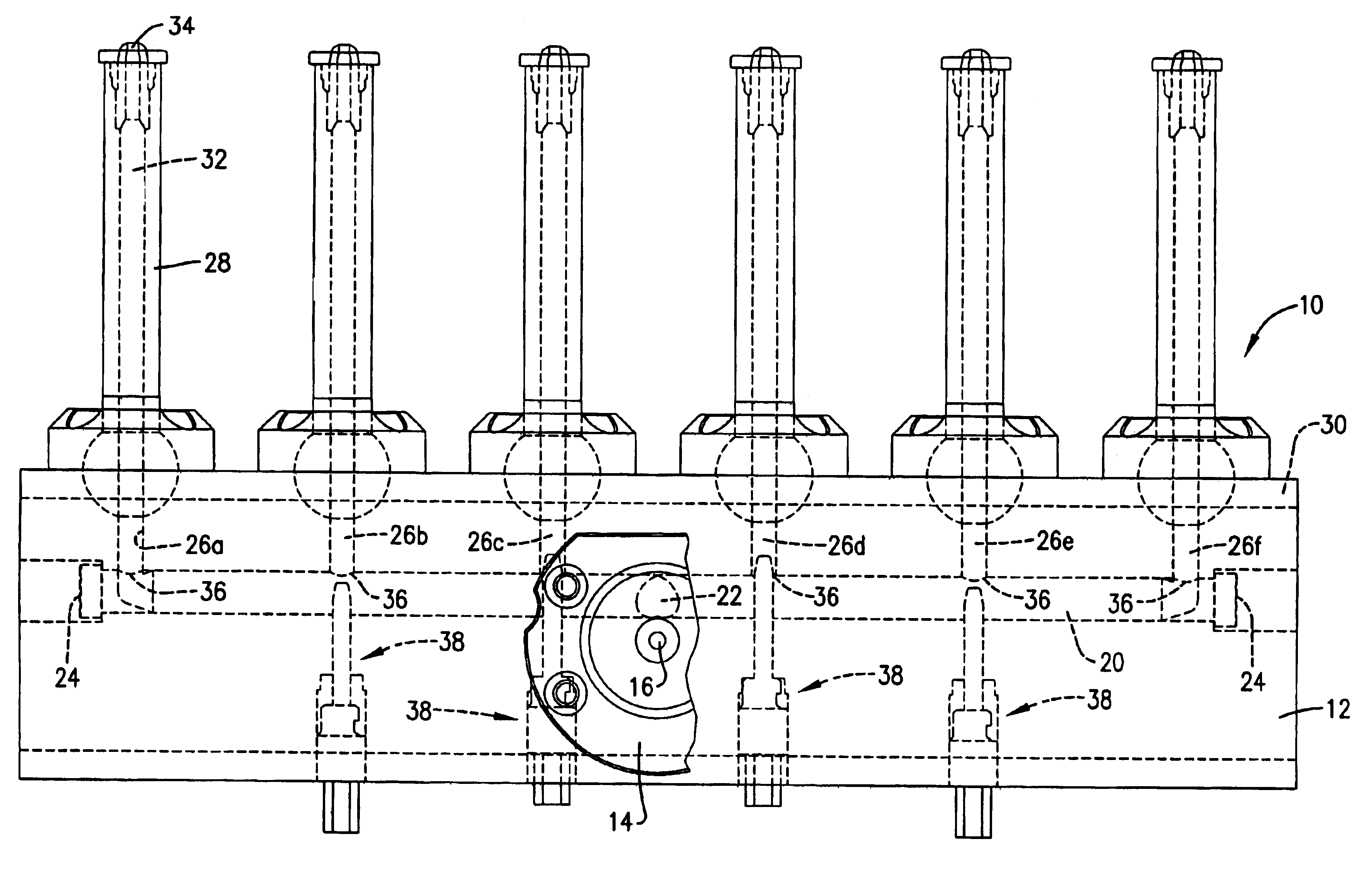
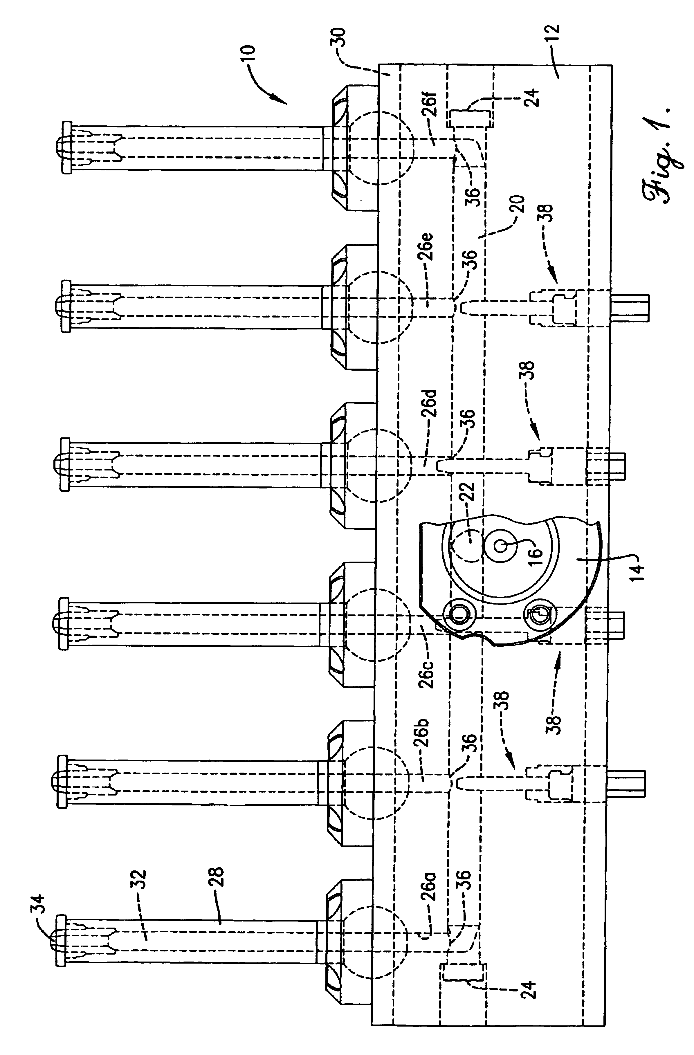
[0010]The manifold 10 comprises a solid parallelepiped body 12 constructed of material having good heat transfer properties such as 4140 high carbon alloy steel. A sprue bushing 14 on the front side of body 12 is adapted to be connected with an extruder (not shown) or other suitable source of supply of molten plastic material. Sprue bushing 14 has an internal passage 16 that communicates with and supplies melt to a slightly upwardly inclined central supply passage 18 within body 12. Passage 18 in turn intersects with a main, longitudinally extending runner 20 to form an inlet 22. Runner 20 extends the full length of bo...


PUM

PropertyMeasurementUnit
hot melt distributionaaaaaaaaaa
lengthaaaaaaaaaa
diameteraaaaaaaaaa

Abstract

An injection manifold has a main runner provided with a supply inlet intermediate opposite ends of the runner. A number of branches intersect with the runner along its length so as to be disposed at unequal distances from the inlet. In order to achieve more simultaneous delivery, uniform fill rate, and identity of temperature of hot melt across all cavities of a multi-cavity set to achieve more uniform cooling of the preforms, restrictor pin assemblies are provided in association with certain of the branches to adjustably constrict the space available for melt flow from the runner into the branch. In a preferred form each restrictor pin assembly includes a pin aligned axially with the branch and passing transversely through the runner, the pin being adjustable between a fully extended, maximum constriction position in which the tip of the pin is located within the branch and a fully retracted, open position in which the tip is withdrawn out of the branch and is spaced below the opening of the branch.

Description

TECHNICAL FIELD[0001]This invention relates to improvements in the technology of making high quality preforms or parisons as part of an injection stretch blow mold (ISBM) or injection blow mold (IBM) process leading to the production of high quality finished PET bottle products. More particularly, it relates to distributing hot melt through a manifold in such a way that the melt reaches all injection cavities of a set thereof at more exactly the same time, rate, and temperature than in the past, resulting in preforms or parisons that cool more uniformly across all of the cavities and, consequently, produce finished bottles of more consistently high quality.BACKGROUND AND SUMMARY[0002]Whether the bottle-making process is an ISBM process where the injected preliminary products are typically referred to as “preforms” or an IBM process where the injected products are typically called “parisons”, the hot melt begins to cool the instant it enters an injection cavity because such cavities ...

Claims


Application Information

Patent Timeline
Patent Type & Authority Patents(United States)
IPC IPC(8): B29C45/32B29C45/27B29C45/30
CPCB29C45/2704B29C2045/2687B29K2105/258
Inventor CHEN, JINCHENG
Owner R & D TOOL & ENG
Why Eureka
Try Eureka