Liquid cartridge

a liquid cartridge and liquid technology, applied in printing and other directions, can solve the problems of known ink jet recording apparatus not being able to estimate the viscosity of ink stored in an ink container, etc., and achieve the effect of estimating the viscosity of liquid stored in the liquid chamber

Active Publication Date: 2016-02-11
BROTHER KOGYO KK
View PDF0 Cites 19 Cited by
  • Summary
  • Abstract
  • Description
  • Claims
  • Application Information

AI Technical Summary

Benefits of technology

[0006]Therefore, a need has arisen for a liquid cartridge which overcomes these and other shortcomings of the related art. A technical advantage of the present invention is that the viscosity of liquid stored in a liquid cartridge may be estimated by more direct measurement.
[0007]According to an aspect of the present invention, a liquid cartridge comprises: a first outer face; a second outer face opposite the first outer face; a liquid chamber positioned between the first outer face and the second outer face and configured to store liquid therein, wherein the liquid has a first specific gravity; a liquid supply portion positioned at the first outer face and configured to supply the liquid from an interior of the liquid chamber to an exterior of the liquid chamber; a movable member positioned in the liquid chamber and comprising a detection portion and a float, wherein the float has a second specific gravity which is less than the first specific gravity; and a restriction member comprising an operation portion and a restriction portion, wherein the operation portion is operable from the exterior of the liquid chamber and movable between a first position and a second position, and the second position is closer to the second outer face than the first position is. The restriction portion is configured to move when the operation portion moves from the first position to the second position. When the operation portion is in the first position, the restriction portion is configured to contact the movable member in the liquid chamber such that movement of the float is restricted within a restricted range and the float is submerged in the liquid in the liquid chamber. When the operation portion is in the second position, the restriction portion is configured to release the movable member such that the float is positioned in a free range which is above the restricted range.
[0008]With this configuration, when the operation portion moves from the first position to the second position, the movable member is released and moves as the float moves within ink. Because the movable member moves against viscous and inertial resistances caused by the liquid in the liquid chamber, the velocity of the detection portion depends on the viscosity of liquid in the liquid chamber. By measuring a physical quantity, based on which the velocity of the detection portion can be specified, the viscosity of liquid stored in the liquid chamber may be estimated.
[0009]According to another aspect of the present invention, a liquid cartridge comprises: a liquid chamber configured to store liquid therein, wherein the liquid has a first specific gravity; a liquid supply portion configured to supply the liquid from an interior of the liquid chamber to an exterior of the liquid chamber; a movable member positioned in the liquid chamber and comprising a detection portion and a float, wherein the float has a second specific gravity which is less than the first specific gravity; and a gas bag filled with gas. The gas bag is configured to change its state from a bulging state to a contracted state. When the gas bag is in the bulging state, the gas bag bulges into the liquid chamber and contacts the movable member in the liquid chamber such that movement of the float is restricted within a restricted range and the float is submerged in the liquid in the liquid chamber. When the gas bag is in the contracted state, the gas bag is configured to release the movable member such that the float is positioned in a free range which is above the restricted range. An amount of gas in the gas bag when the gas bag is in the contracted state is less than an amount of gas in the gas bag when the gas bag is in the bulging state.
[0010]With this configuration, when the gas bag changes its state from the bulging state to the contracted state, the movable member is released and moves as the float moves within ink. Because the movable member moves against viscous and inertial resistances caused by the liquid in the liquid chamber, the velocity of the detection portion depends on the viscosity of liquid in the liquid chamber. By measuring a physical quantity, based on which the velocity of the detection portion can be specified, the viscosity of liquid stored in the liquid chamber may be estimated.

Problems solved by technology

Nevertheless, this known ink-jet recording apparatus does not estimate the viscosity by directly measuring a physical quantity obtained when a movable member moves in ink.
Moreover, this known ink jet recording apparatus cannot estimate the viscosity of ink stored in an ink container which has not been mounted to the ink-jet recording apparatus and been unused.

Method used


Image

  • Liquid cartridge
  • Liquid cartridge
  • Liquid cartridge

Examples


first modified embodiment

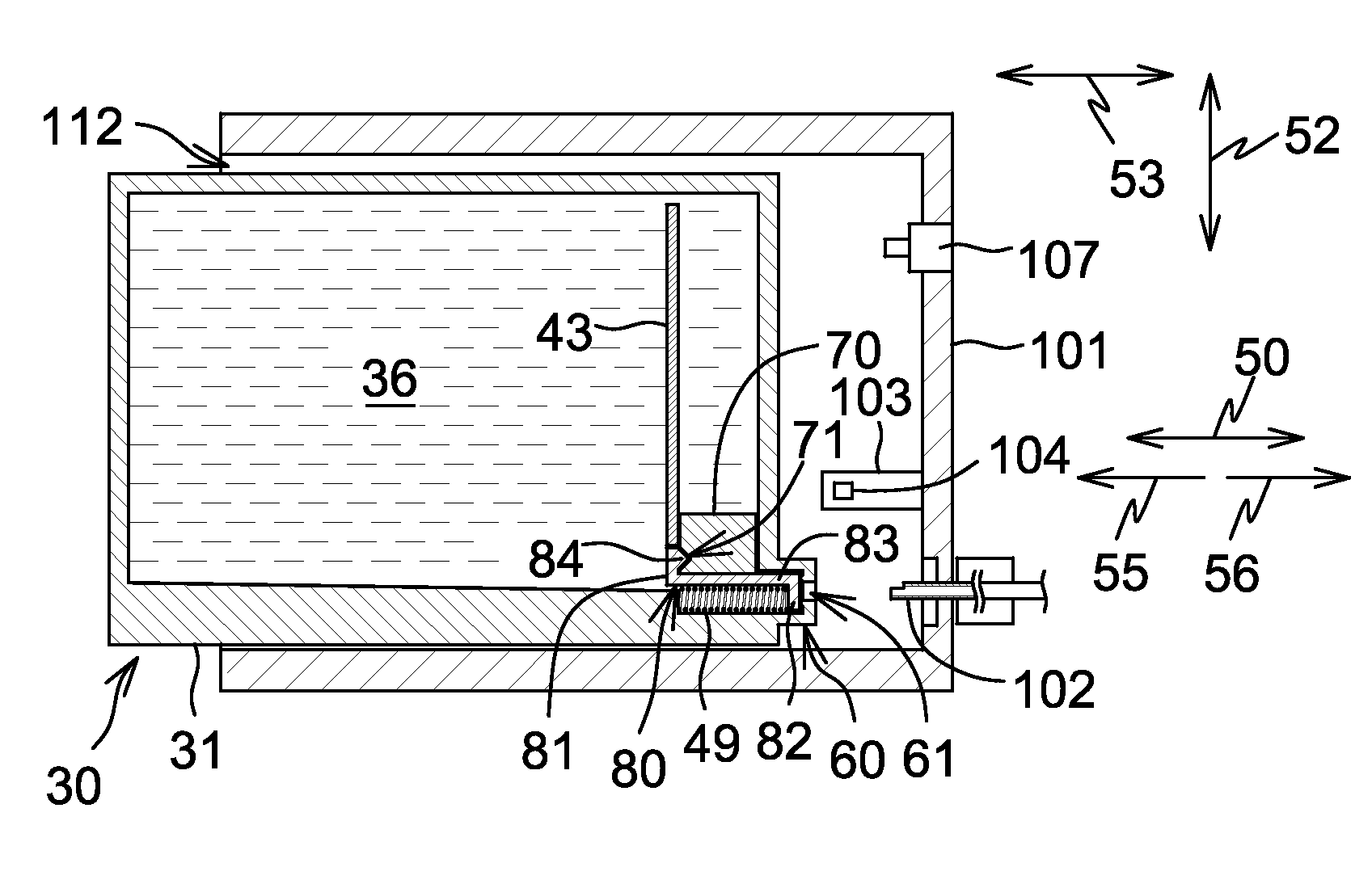
[0102]Referring to FIG. 9, an ink cartridge 30 according to a first modified embodiment is described. The descriptions of the parts which are common between the above-described embodiment and the first modified embodiment may be omitted, but the parts of the first modified embodiment which are different from the parts of the above-described embodiment are described. Similarly, the descriptions of the parts which are common among the above-described embodiment, the first modified embodiment, and the later-described further modified embodiments may be omitted if they are once described. Moreover, the parts of the above-described embodiment, the first modified embodiment, and the later-described further modified embodiments can be arbitrarily combined as long as the object of the invention is achieved.

[0103]In the ink cartridge 30 according to the first modified embodiment, the movable member (float, detection portion, light blocking portion) 70 is connected to the restriction portion ...

second modified embodiment

[0105]Referring to FIGS. 10A and 10B, an ink cartridge 30 and a cartridge mounting portion 110 according to a second modified embodiment are described. The controller 130 determines that the movable member (float, detection portion, light blocking portion) 70 is released from the restriction portion 81 when the mount sensor 107 outputs the signal indicating that the ink cartridge 30 is in the mount position. In other words, the controller 130 determines that the movable member (float, detection portion, light blocking portion) 70 is released from the restriction portion 81 at a timing when the detection signal output from the mount sensor 107 changes from the signal indicating that the ink cartridge 30 is not in the mount position to the signal indicating that the ink cartridge 30 is in the mount position.

[0106]The timing when the movable member (float, detection portion, light blocking portion) 70 is released from the restriction portion 81 and the timing when the mount sensor 107 ...

third modified embodiment

[0110]Referring to FIGS. 11A and 11B, an ink cartridge 30 and a cartridge mounting portion 110 according to a third modified embodiment are described. The restriction member of the ink cartridge 30 comprises a gas bag 85 positioned in the front wall 40. The gas bag 85 is penetrated through the front wall 40 in the depth direction 53. The gas bag 85 is filled with gas and bulges into the ink chamber 36. The state of the gas bag 85 is called a bulging state. The gas bag 85 in the bulging state contacts the upper end of the movable member (float, detection portion, light blocking portion) 70 and thereby functions as a restriction member restricting the movement of the movable member (float, detection portion, light blocking portion) 70. The restriction portion 81 and the connection portion 83 are omitted in the ink cartridge 30 according to the third modified embodiment, and the operation portion 82 is replaced with a valve configured to selectively open and close the ink supply openin...


PUM


Abstract

A liquid cartridge includes a movable member and the movable member includes a detection portion and a float. The liquid cartridge also includes a restriction member and the restriction member includes an operation portion and a restriction portion. When the operation portion is in a first position, the restriction portion is configured to contact the movable member such that the movement of the float is restricted within a restricted range. When the operation portion is in a second position, the restriction portion is configured to release the movable member such that the float is positioned in a free range which is above the restricted range.

Description

CROSS REFERENCE TO RELATED APPLICATION[0001]The present application claims priority to and the benefit of European Patent Application No. 14180069.8, which was filed on Aug. 6, 2014, the disclosure of which is incorporated herein by reference in its entirety.BACKGROUND OF THE INVENTION[0002]1. Field of the Invention[0003]The present invention relates to a liquid cartridge.[0004]2. Description of Related Art[0005]A known ink jet recording apparatus is configured to record an image on a recording medium by ejecting ink stored in an ink container from nozzles. The viscosity of ink stored in the ink container may change over time. A known ink-jet recording apparatus, as described in Patent Application Publication No. JP-09-277560 A, is configured to estimate the viscosity of ink stored in an ink container, and perform optimized preliminary ejection based on the result of the estimation. More specifically, the ink-jet recording apparatus is configured to estimate the viscosity of ink bas...

Claims


Application Information

Patent Timeline
Patent Type & Authority Applications(United States)
IPC IPC(8): B41J2/175
CPCB41J2/1752B41J2/17566B41J2002/17576
Inventor SUGAHARA, HIROTOHAYASHIDA, KENTANAGANO, TAROOHISHI, AYAKOKONDO, HIROFUMITOMOGUCHI, SUGURU
Owner BROTHER KOGYO KK
Why Eureka
Try Eureka