Turbine blade mid-span shroud

Active Publication Date: 2016-02-11
GENERAL ELECTRIC CO
View PDF2 Cites 0 Cited by
  • Summary
  • Abstract
  • Description
  • Claims
  • Application Information

AI Technical Summary

Problems solved by technology

More specifically, the turbine blades may experience fluctuating forces when they rotate through non-uniform fluid flow downstream from stationary vanes, also known as nozzles, positioned between adjacent rows of turbine blades.
However, mid-span shrouds are typically cast as part of the turbine blade and may require additional machining or other finishing processes to produce a finished turbine blade.
This may only be cost-effectiv

Method used


Image

  • Turbine blade mid-span shroud
  • Turbine blade mid-span shroud
  • Turbine blade mid-span shroud

Examples


Example

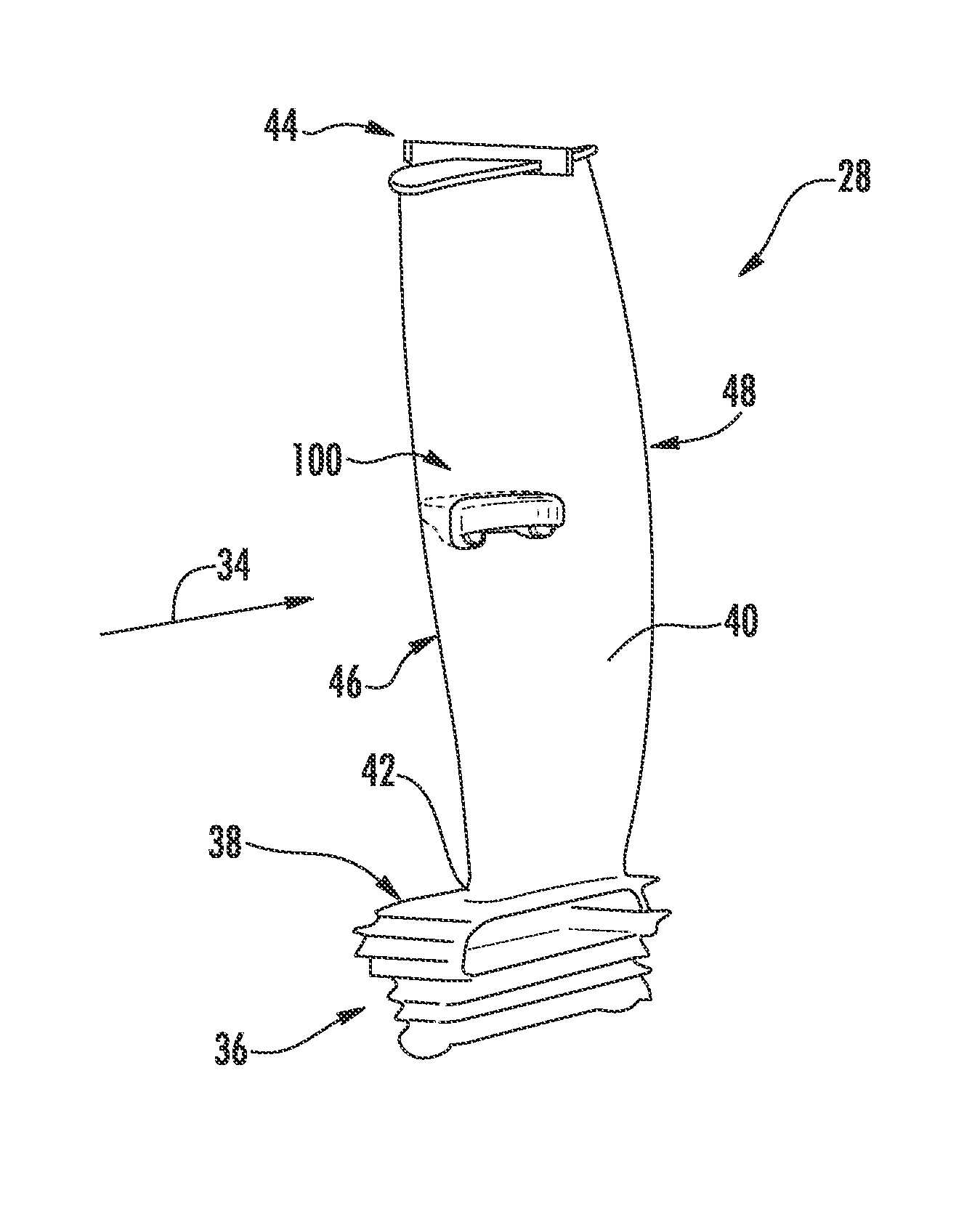
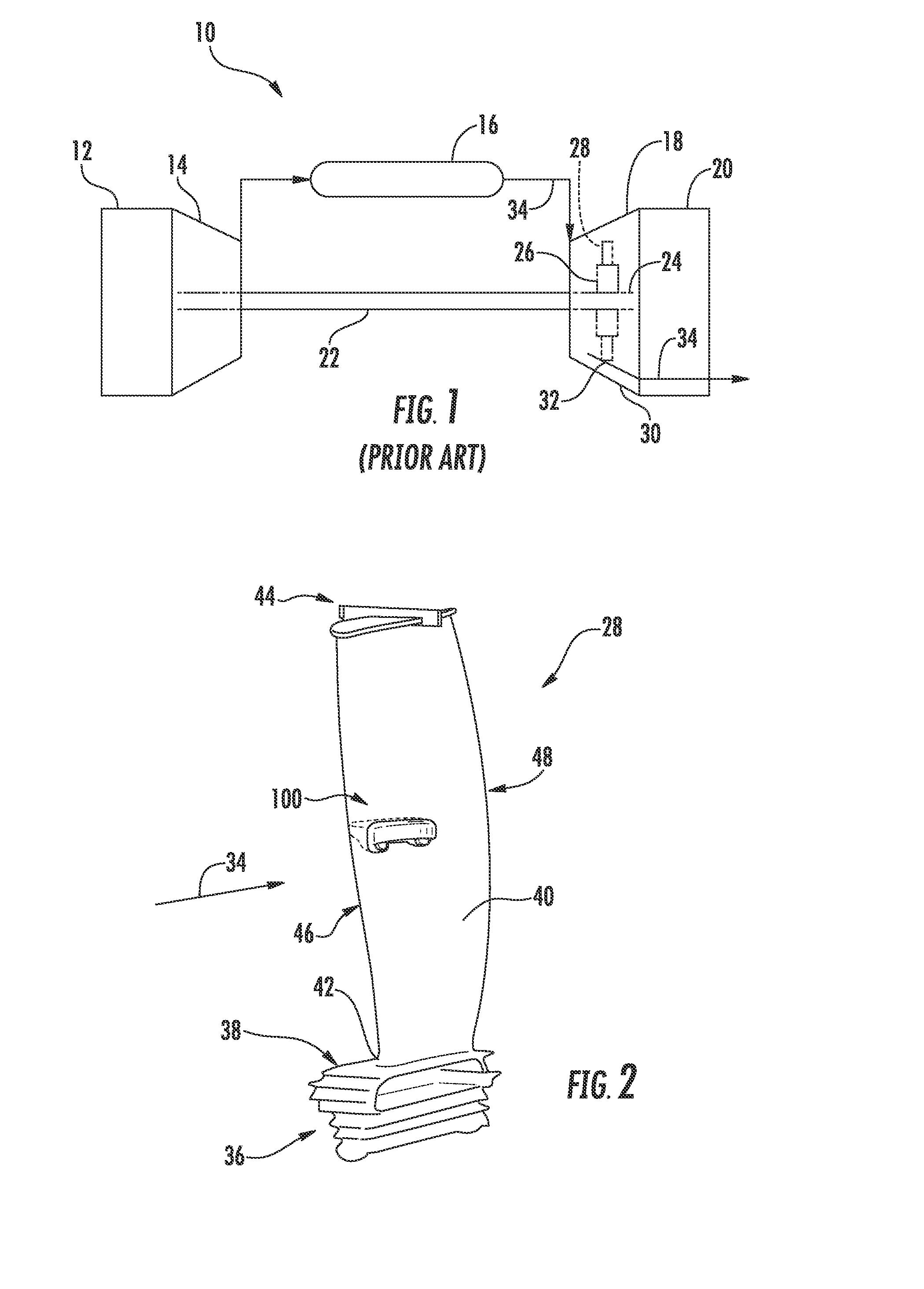
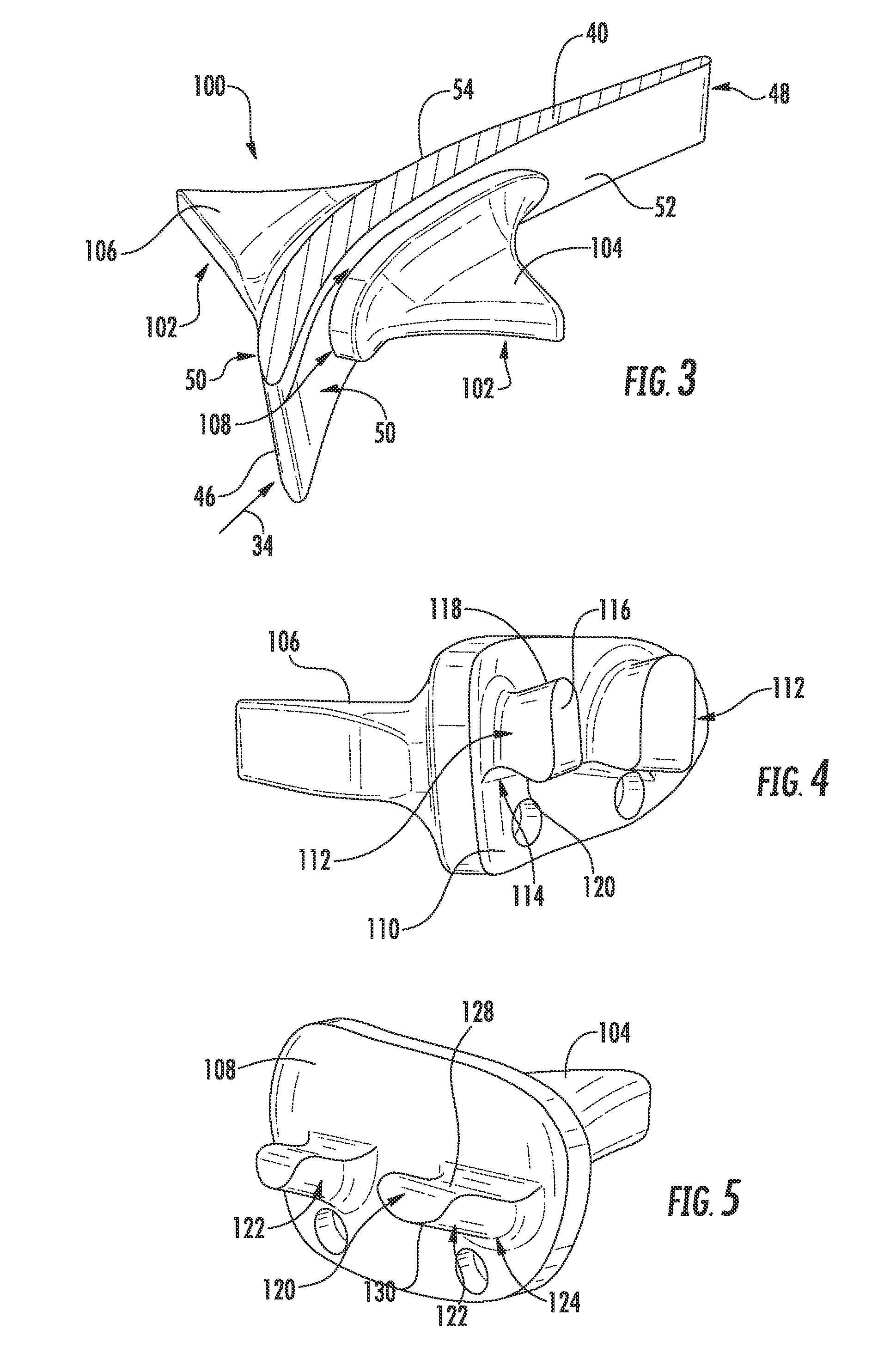
[0023]Reference will now be made in detail to present embodiments of the invention, one or more examples of which are illustrated in the accompanying drawings. The detailed description uses numerical and letter designations to refer to features in the drawings. Like or similar designations in the drawings and description have been used to refer to like or similar parts of the invention. As used herein, the terms “first”, “second”, and “third” may be used interchangeably to distinguish one component from another and are not intended to signify location or importance of the individual components. The terms “upstream” and “downstream” refer to the relative direction with respect to fluid flow in a fluid pathway. For example, “upstream” refers to the direction from which the fluid flows, and “downstream” refers to the direction to which the fluid flows. The term “radially” refers to the relative direction that is substantially perpendicular to an axial centerline of a particular compone...


PUM


Abstract

A mid-span shroud assembly comprises a suction side shroud body which defines a first spar. The first spar is formed to extend at least partially through a spar opening defined within the airfoil and includes a root portion, a tip portion, an upper face and a lower face. The upper and lower faces converge from the tip portion towards the root portion. The mid-span assembly further includes a pressure side shroud body. The pressure side shroud body defines a second spar which is formed to extend at least partially through the spar opening of the airfoil and includes a root portion, a tip portion, an upper face and a lower face. At least a portion of the upper face of the second spar is formed to be substantially parallel with the lower face of the first spar when both the first and second spars are inserted into the spar opening.

Description

FIELD OF THE INVENTION[0001]The present invention generally relates to a turbine blade. More particularly, this invention involves a mid-span shroud assembly for the turbine blade.BACKGROUND OF THE INVENTION[0002]A rotating turbine blade, also known as a turbine bucket or turbine rotor blade, converts energy from a flowing fluid such as hot combustion gas or steam into mechanical energy by causing a shaft of a turbomachine to rotate. As the turbomachine transitions through various operating modes, the turbine blades are subjected to both mechanical and thermal stresses.[0003]Mechanical stresses, such as fatigue, may be caused by fluctuating forces in combination with steady state forces. More specifically, the turbine blades may experience fluctuating forces when they rotate through non-uniform fluid flow downstream from stationary vanes, also known as nozzles, positioned between adjacent rows of turbine blades. A basic design consideration for turbomachines is to avoid or to minimi...

Claims


Application Information

Patent Timeline
IPC IPC(8): F01D5/22
CPCF01D5/22F01D5/147F01D5/225Y02T50/60
Inventor COLLINS, DARYL R.BUTZ, DAVID ARTHUR
Owner GENERAL ELECTRIC CO
Why Eureka
Try Eureka