
Remote control arrangement

a remote control and remote technology, applied in the field of remote control, can solve the problems of user interface not allowing the user to see the actual state of the device, infrared technology with radio frequency (rf) technology on the push button remote does not make the system more useful in regards to confirmation,

Inactive Publication Date: 2016-02-11
XPED HLDG
View PDF1 Cites 9 Cited by
  • Summary
  • Abstract
  • Description
  • Claims
  • Application Information

AI Technical Summary

Benefits of technology

The invention is a system that includes a remote control device with a meta-state widget that indicates the condition of application widgets on a graphical user interface. The meta-state widget can indicate that an associated entity has been commanded to change state but has not confirmed the change state. The system can also provide indications using visual, auditory, or tactile means. The associated entity can be located on the same device or a remote device connected by a communications mechanism. The invention allows for the duration of time for an associated entity to respond to a command to be specified. The technical effect of the invention is to provide a system that allows for convenient and efficient control of application widgets on a graphical user interface.

Problems solved by technology

As more devices become remotely controllable, especially over communications links such as Personal Area Networks (PAN), Wireless Local Area Networks (WLAN) and cellular telephone networks, it is a significant challenge to keep the user informed of the true state of the devices they are attempting to monitor and control.
This situation is especially important when the user is at a remote location or in a different room to the device being controlled such that they cannot observe whether a command was actioned or not.
Simply replacing infrared technology with Radio Frequency (RF) technology on a push button remote does not make the system more useful with regards to the confirmation of the actioned command.
However, this kind of user interface does not allow the user to see the actual state of the device on the remote control.
However, displaying the state of a device on a remote controller connected to it via communications link introduces a number of problems.

Method used


Image

  • Remote control arrangement
  • Remote control arrangement
  • Remote control arrangement

Examples


Embodiment Construction

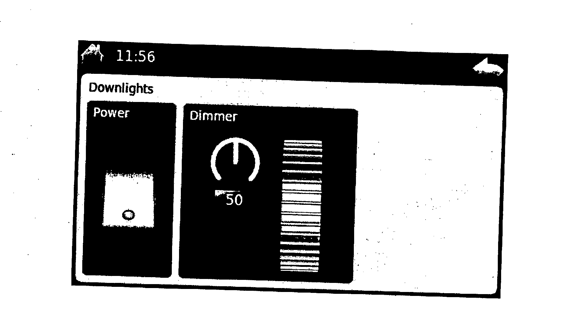
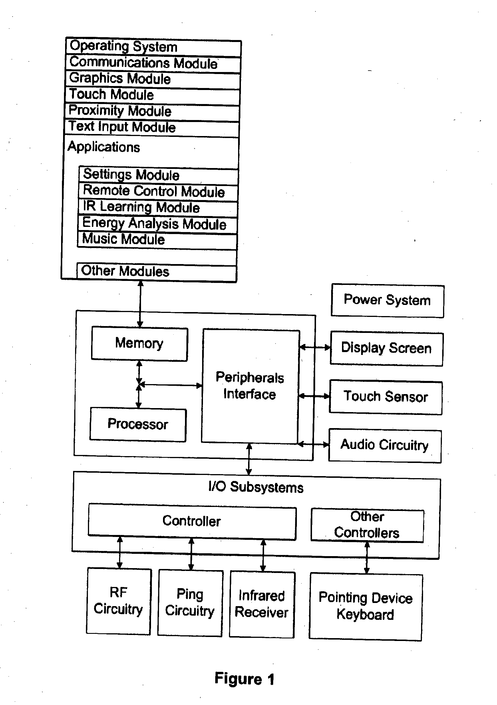
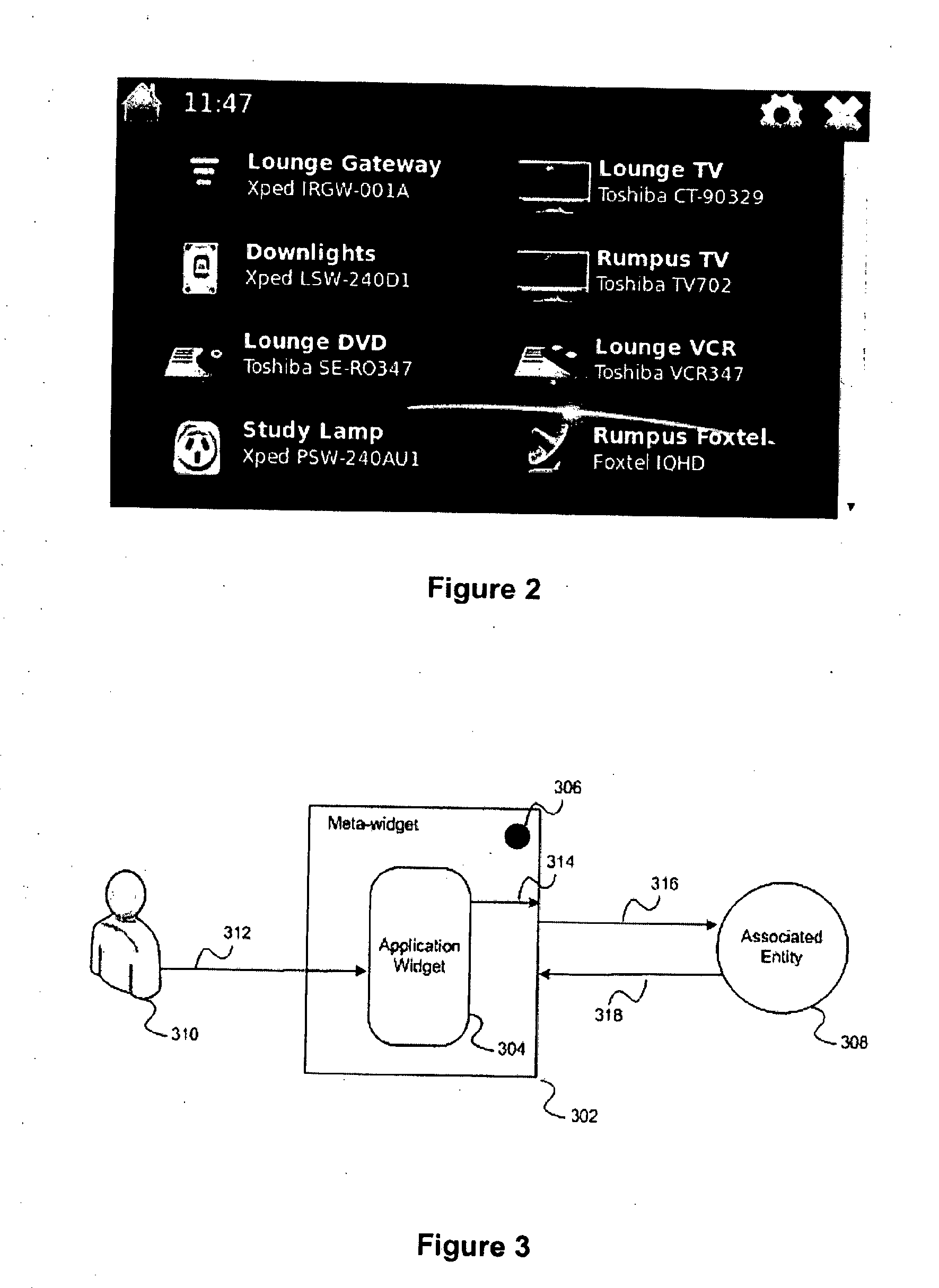
[0032]The disclosed embodiments relate generally to remote controls with graphical user interfaces and user input mechanisms that are used to control the state of one or more other devices. In this specification, the term device may refer to physical hardware (e.g. a Personal Video Recorded (PVR)) or a suitable light fitting, a software application or a complex system within a suitable computer equipped device.

[0033]Embodiments of a multifunction control device, user interfaces for such devices and associated processes for using such devices are described. In some embodiments, the device is a portable device such as a tablet computer or a mobile phone that also contains other functions such as a music player or calendar. The user interface may include a touchscreen or some other human input device such as a keyboard, mouse or even a joystick. However in all embodiments, the device has a display capable of showing a graphical user interface however this is a desirable feature to ease...


PUM


Abstract

The invention relates generally to remote controls with graphical user interfaces and user input mechanisms that are used to control the state of one or more other devices. The invention includes a meta-state widget provided on a remote control device to indicate a condition of the state of an application widget also on the device. An application widget provides on the remote control a visual icon such as a push button, slider, check box or other kind of icon that commonly appears on a graphical user interface. An application widget may be used to send a command to an associated entity to cause it to change state. In general an associated entity may be a physical device such as a PVR, or a software element such as a program or a component of a program. The conditions that may be indicated on the remote control device by the meta-state widget are: UNCONFIRMED, CONFIRMED, UNKNOWN and IN-ERROR.

Description

CROSS REFERENCE TO RELATED APPLICATION[0001]This application claims priority from U.S. Provisional Application 61 / 772666 filed Mar. 5, 2013 the disclosures of which are herein incorporated by reference in their entirety.TECHNICAL FIELD[0002]The invention relates generally to remote controls with graphical user interfaces and user input mechanisms that are used to control the state of one or more other devices.BACKGROUND[0003]As more devices become remotely controllable, especially over communications links such as Personal Area Networks (PAN), Wireless Local Area Networks (WLAN) and cellular telephone networks, it is a significant challenge to keep the user informed of the true state of the devices they are attempting to monitor and control. This situation is especially important when the user is at a remote location or in a different room to the device being controlled such that they cannot observe whether a command was actioned or not.[0004]The most common remote control technolog...

Claims


Application Information

Patent Timeline
IPC IPC(8): G06F3/0481G06F3/0484G06F3/0488
CPCG06F3/04817G06F3/04847G06F3/04842G06F3/0488H04N21/42204H04N21/43615H04N21/43637H04N21/44231H04N21/4882H04N21/8186H04N21/41265
Inventor WOOD, CHRISTOPHER RICHARDSCHULTZ, JOHN COLIN
Owner XPED HLDG
Learn More