Diaphragm pump integrally including quick discharge valve unit

a technology of diaphragm pump and quick discharge valve, which is applied in the direction of pump components, positive displacement liquid engines, liquid fuel engine components, etc., can solve the problem of unstable pressurization to the pressurization target, and achieve the effect of stabilizing the pressurization targ

Active Publication Date: 2016-02-18
OKEN LTD
View PDF3 Cites 3 Cited by
  • Summary
  • Abstract
  • Description
  • Claims
  • Application Information

AI Technical Summary

Benefits of technology

[0011]It is an object of the present invention to provide a diaphragm pump integrally including a quick discharge valve unit and still capable of stably pressurizing a pressurization target.

Problems solved by technology

If the flow rate of air to be delivered to the pressurization target decreases, therefore, pressurization to the pressurization target becomes unstable.

Method used


Image

  • Diaphragm pump integrally including quick discharge valve unit
  • Diaphragm pump integrally including quick discharge valve unit
  • Diaphragm pump integrally including quick discharge valve unit

Examples


Embodiment Construction

[0019]An embodiment of the present invention will be explained below with reference to FIGS. 1 to 5.

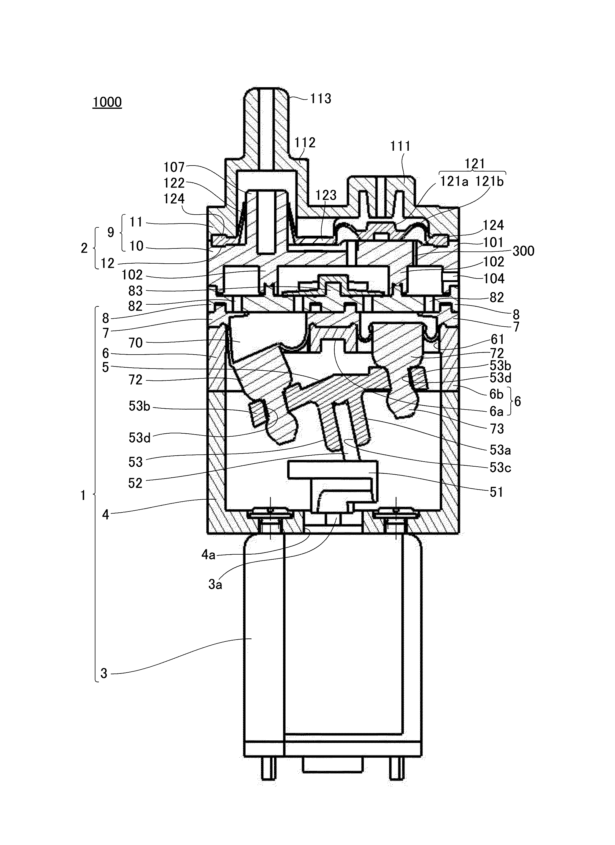
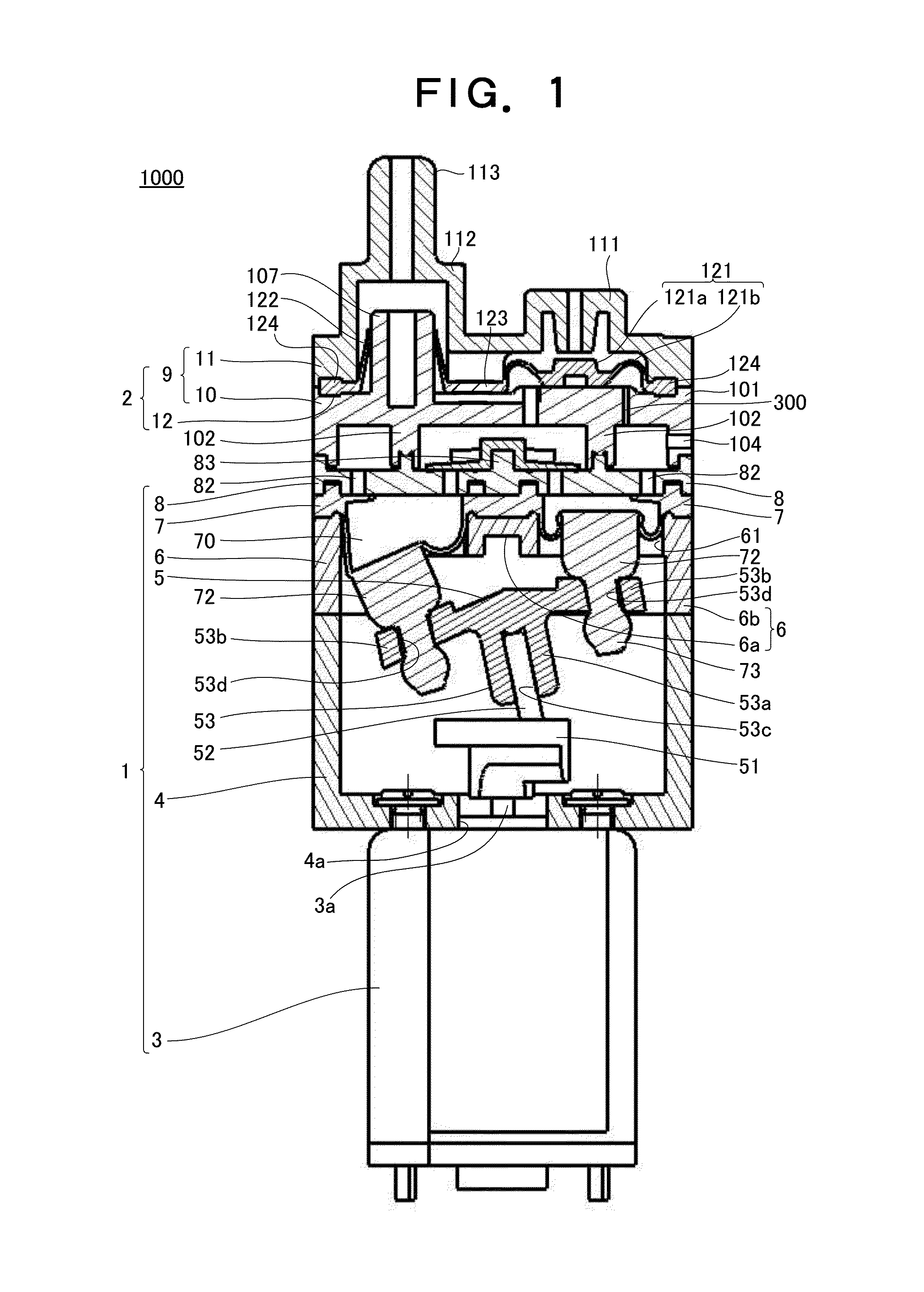
[0020]As shown in FIG. 1, a diaphragm pump 1000 according to this embodiment includes a diaphragm pump main body 1 and quick discharge valve unit 2.

[0021]The diaphragm pump main body 1 includes a motor 3, a case 4 to which the motor 3 is fixed, a driving mechanism 5 accommodated in the case 4, a diaphragm holder 6 formed on the case 4, a diaphragm 7 held by the diaphragm holder 6, and a partition member 8 formed on the diaphragm 7.

[0022]The case 4 is a bottomed cylindrical member having one open end and one closed end. In this embodiment, the bottom portion of the case 4 has an almost square shape in a planar view. The case 4 is made of, e.g., a resin. The motor 3 is fixed to the bottom portion of the case 4 from outside the case 4. An output shaft 3a of the motor 3 is inserted into the case 4 from a hole 4a formed in the bottom portion of the case 4, and connected to the driving mech...


PUM


Abstract

A diaphragm pump includes a quick discharge valve unit that comprises a vessel including a supply passage, a check valve seat, a delivery passage and a discharge passage, and an elastic member configured to partition an internal space of the vessel into an input-side space connected to the supply passage and an output-side space connected to the delivery passage and the discharge passage. The elastic member includes a check valve body to prevent an inflow of air from the output-side space to the input-side space, and a discharge port valve body configured to close the discharge passage when air is supplied to the input-side space through the supply passage. The vessel includes a connecting path having a sectional area smaller than an area of a section of the supply passage, and configured to release pressurized air in the input-side space to an outside.

Description

BACKGROUND OF THE INVENTION[0001]The present invention relates to a diaphragm pump integrally including a quick discharge valve unit.[0002]A diaphragm pump is generally used to supply pressurized air to a pressurization target such as a sphygmomanometer. The diaphragm pump is a pump which delivers air to a pressurization target by deforming a diaphragm portion made of an elastic material. A quick discharge valve unit is integrated with a delivery port of the diaphragm pump like this. When the operation of the diaphragm pump is stopped, the quick discharge valve unit discharges pressurized air remaining in a pressurization target within a short time (e.g., Japanese Patent Laid-Open No. 2012-172577 (see patent literature 1)).[0003]FIG. 6 shows an example of the conventional diaphragm pump integrally including the quick discharge valve unit.[0004]A diaphragm pump 100 includes a diaphragm 7 including a plurality of diaphragm portions 71, a partition member 8 formed on the diaphragm 7, a...

Claims


Application Information

Patent Timeline
Patent Type & Authority Applications(United States)
IPC IPC(8): F04B53/10F04B45/04
CPCF04B45/04F04B53/1072F04B45/043F04B45/045
Inventor FUKAMI, TADASHI
Owner OKEN LTD
Why Eureka
Try Eureka