Vertical shaft foundation thermal drainage consolidation test device

A technology of consolidation test and hot drainage, which is applied in measuring devices, using stable tension/pressure testing material strength, instruments, etc. The effect of large pressure load, good reliability and high degree of automation

Active Publication Date: 2021-12-28
ZHEJIANG UNIV
View PDF11 Cites 2 Cited by
  • Summary
  • Abstract
  • Description
  • Claims
  • Application Information

AI Technical Summary

Problems solved by technology

[0002] The existing shaft drainage consolidation test device, as disclosed in the application number CN201410686099.5, uses the principle of leverage and weights and other heavy objects to directly pressurize. Its structure is relatively simple, but manual control is required, and the pressurization The accuracy is poor, and the pressurization pressure is small; and it is only heated through the built-in U-shaped heat pipe, and there is a problem of uneven heating

Method used


Image

  • Vertical shaft foundation thermal drainage consolidation test device
  • Vertical shaft foundation thermal drainage consolidation test device
  • Vertical shaft foundation thermal drainage consolidation test device

Examples


Embodiment 1

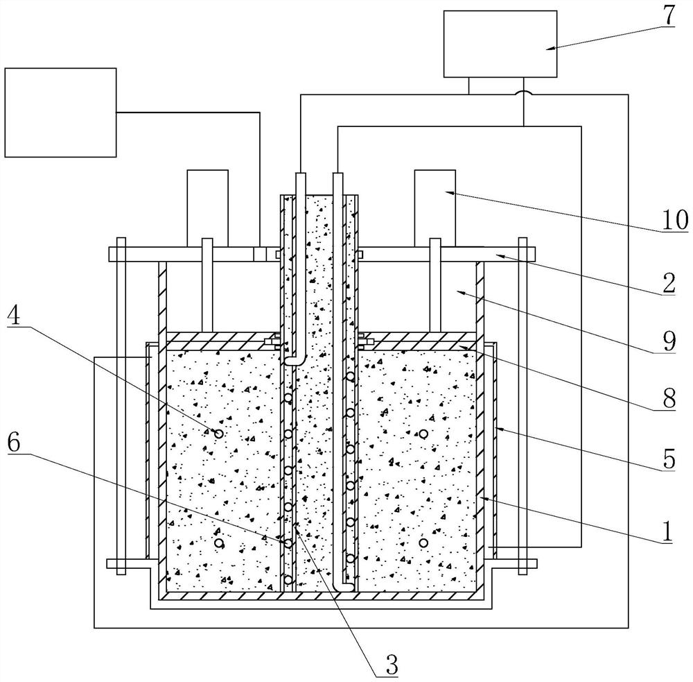
[0063] A shaft foundation thermal drainage consolidation test device is characterized in that it includes:

[0064] A test box 1, the top of the test box 1 is provided with a box cover 2, and soil samples are filled in the test box 1;

[0065] A pressurizing mechanism for loading and compacting the soil sample;

[0066] Drainage mechanism, including the vertical shaft 3 arranged in the test chamber 1;

[0067] A heating mechanism for heating the soil sample;

[0068] Wherein, the pore water pressure sensor 4 is pre-buried in the soil sample; the heating mechanism includes a first heating assembly arranged on the outer wall of the test chamber 1 and a second heating assembly arranged on the outer wall of the shaft 3 .

[0069] The box cover 2 and the test box 1 can be fixedly connected by a plurality of screws, and the outside and the center of the test box 1 are jointly heated, so that the heating uniformity is good, and the detection accuracy of the test can be improved.

Embodiment 2

[0071] In this embodiment, in addition to the structural features of the preceding embodiments, the further first heating assembly includes a jacket 5 arranged on the outer wall of the test chamber 1, and an insulation layer is provided outside the jacket 5;

[0072] The second heating assembly includes a heating coil 6;

[0073] The heating mechanism also includes a heating unit 7 for heating the jacket 5 and the heating coil 6;

[0074] The heat supply unit 7 is used to provide the heat medium at the required temperature. The heat supply unit 7 can be an external water tank or heat transfer oil tank with heating function, and the circulating hot water or heat conduction is delivered through the circulating pump box jacket 5 and the heating coil 6 Oil.

[0075] The shaft 3 is an inner and outer double-layer cylinder, and the heating coil 6 is arranged between the two layers of cylinders, and the water inlet end of the heating coil 6 radially penetrates the inner cylinder and...

Embodiment 3

[0078] In this embodiment, in addition to the structural features of the preceding embodiments, the pressurizing mechanism further includes:

[0079] Pressure plate 8, the pressure plate 8 is located in the test box 1, and the main pressure chamber 9 is formed between the pressure plate 8 and the box cover 2;

[0080] Auxiliary cylinder 10, the number of auxiliary cylinders 10 is evenly installed on the top of the box cover 2, and the cylinder rod of the auxiliary cylinder 10 is installed through the box cover 2 and connected with the pressure plate 8, and the cylinder rods are mounted on the pressure plate in a circular equidistant manner 8 on the perimeter;

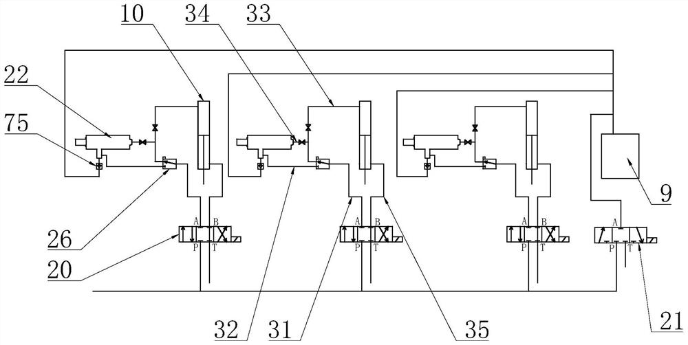
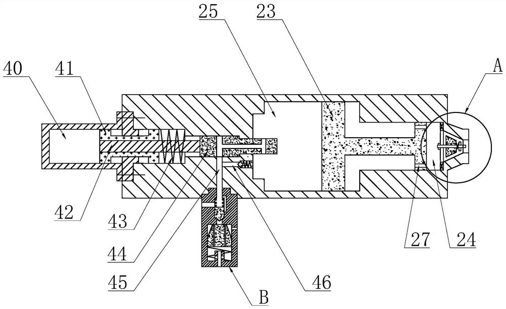
[0081] The air control unit is used to control the intake and exhaust of the main pressure chamber 9 and the auxiliary cylinder 10;

[0082] Wherein, the box cover 2 is provided with air holes communicated with the main pressure chamber 9, the pressure plate 8 is an upper and lower double-layer structure, and the cente...


PUM


Abstract

The invention discloses a vertical shaft foundation thermal drainage consolidation test device, which can measure the influence of temperature on consolidation under the condition of rated pressure load so as to count each group of measuring data and comprehensively analyze the influence of each factor on soil sample consolidation, and can realize automatic loading measuring, and the vertical shaft foundation thermal drainage consolidation test device comprises a test box, a pressurizing mechanism, a drainage mechanism , and a heating mechanism ; a box cover is arranged at the top of the test box, and the test box is filled with a soil sample; the pressurizing mechanism is used for loading and pressing the soil sample; the drainage mechanism comprises a vertical shaft arranged in the test box; the heating mechanism is used for heating the soil sample; wherein a pore water pressure sensor is pre-buried in the soil sample; and the heating mechanism comprises a first heating assembly arranged on the outer wall of the test box and a second heating assembly arranged on the outer wall of the vertical shaft.

Description

technical field [0001] The invention belongs to the technical field of geotechnical tests, in particular to a thermal drainage consolidation test device for a shaft foundation. Background technique [0002] The existing shaft drainage consolidation test device, as disclosed in the application number CN201410686099.5, uses the principle of leverage and weights and other heavy objects to directly pressurize. Its structure is relatively simple, but manual control is required, and the pressurization The accuracy is poor, and the pressurization pressure is small; and it only heats through the built-in U-shaped heat pipe, and there is a problem of uneven heating. Contents of the invention [0003] The purpose of the present invention is to provide a thermal drainage consolidation test device for shaft foundation, which can measure the influence of temperature on consolidation under the condition of rated pressure load, so as to count the measurement data of each group and compre...

Claims


Application Information

Patent Timeline
Patent Type & Authority Applications(China)
IPC IPC(8): G01N3/08G01N3/02
CPCG01N3/08G01N3/02G01N2203/0019G01N2203/0222
Inventor 闻敏杰吴君涛
Owner ZHEJIANG UNIV
Why Eureka
Try Eureka