Toner conveying member, developing device, and image forming apparatus

a technology of developing device and conveying member, which is applied in the direction of electrographic process apparatus, instruments, optics, etc., can solve the problems of preventing axially smooth conveying of developer, affecting the accuracy of toner concentration sensor output, and increasing the cost, so as to reduce the bending or preventing the bending of the toner conveying member, increase durability, and reduce the effect of material cos

Active Publication Date: 2016-02-25
SHARP KK
View PDF3 Cites 1 Cited by
  • Summary
  • Abstract
  • Description
  • Claims
  • Application Information

AI Technical Summary

Benefits of technology

[0020]Preferred embodiments of the present invention reduce or prevent bending of a toner conveying member caused by rotational drive, achieve increased durability, and significantly reduce material cost.

Problems solved by technology

Therefore, although this technique stabilizes the output of the toner concentration sensor, it causes a problem that a developer conveyed over the detecting surface adheres to the detecting surface such as when the electrical charge of toner increases too much, and thus the correct output of the toner concentration sensor cannot be obtained.
Further, with this technique, a metal shaft is present along the entire longitudinal length, which eliminates a problem such as deformation or breakage due to drive stress but causes a problem such as a cost increase.
However, a toner conveying member with a shaft made of resin as described in JP 2014-115402 A permanently deforms relatively early at the shaft of the resin material, preventing a developer from being conveyed axially smoothly.
Thus, in view of the recovery and recycle of cartridges, it causes a new problem that the number of recyclability of the toner conveying member decreases.
Stress under this state causes a troublesome phenomenon such as rubbing against an inner wall of the development container, the wear of a drive transmission gear, or a deformation at a bearing portion and the vicinity.

Method used


Image

  • Toner conveying member, developing device, and image forming apparatus
  • Toner conveying member, developing device, and image forming apparatus
  • Toner conveying member, developing device, and image forming apparatus

Examples


first preferred embodiment

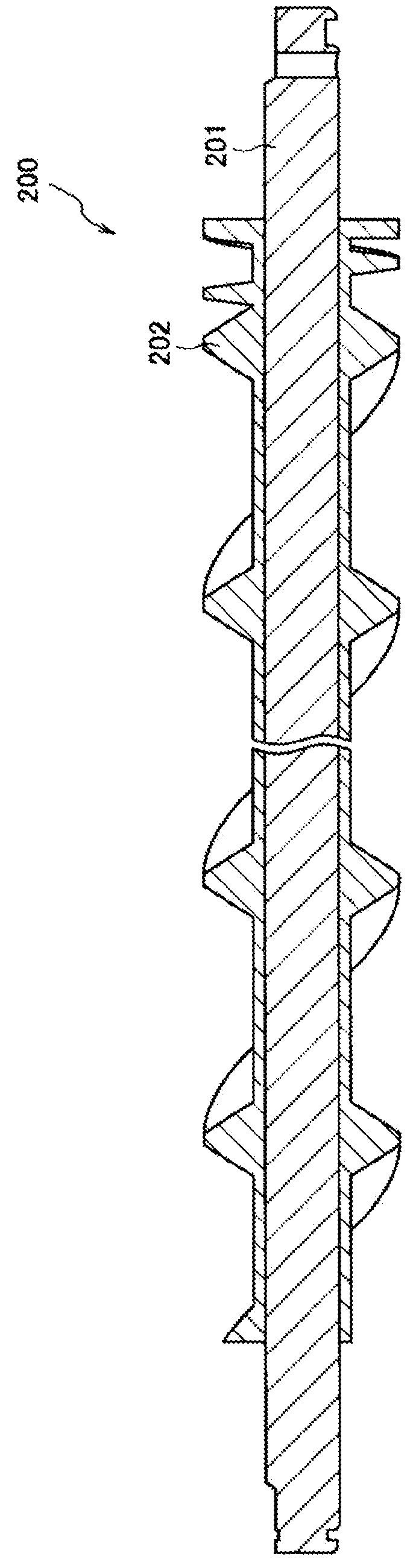
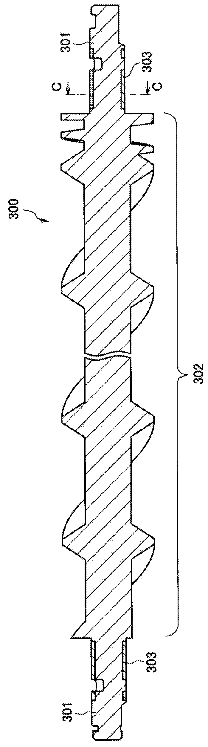
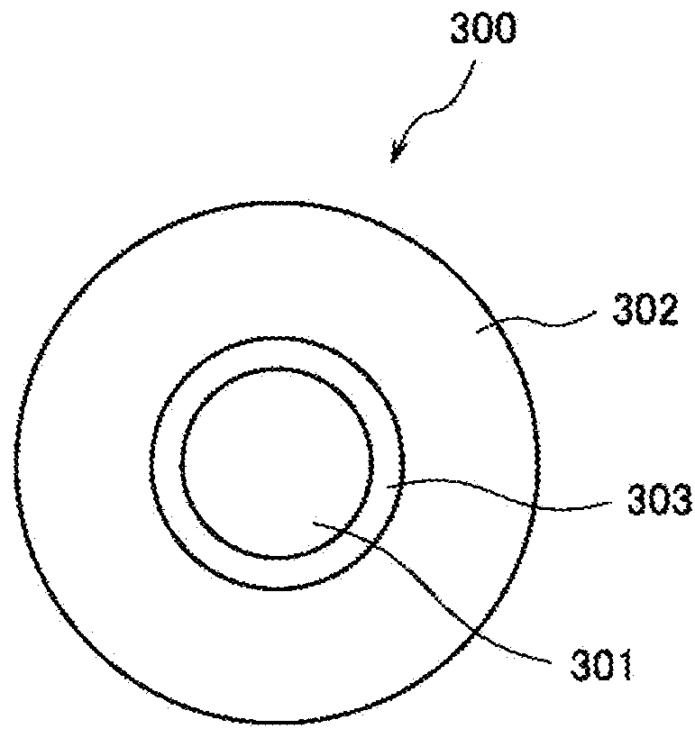
[0041]A first preferred embodiment of the present invention will be described with reference to FIGS. 3A to 5. FIG. 3A is a view showing an example of a toner conveying member according to the first preferred embodiment of the present invention, FIG. 3B is an enlarged view showing an axial cross-sectional shape of the toner conveying member in FIG. 3A, FIG. 3C is a cross-sectional view in the direction C-C in FIG. 3B, FIG. 3D is a cross-sectional view in the direction D-D in FIG. 3B, and FIG. 3E is a cross-sectional view in the direction E-E in FIG. 3B.

[0042]A toner conveying member 1 according to this preferred embodiment is a member with a shaft 11 and a screw integrally molded with resin. The shaft 11 has a length that is equal or substantially equal to the length of the toner conveying member 1. For the resin, for example, high impact polystyrene (HIPS), acrylonitrile butadiene styrene copolymer synthetic resin (ABS), polycarbonate (PC), or a mixture of those resins (into which ...

second preferred embodiment

[0091]A toner conveying member according to a second preferred embodiment of the present invention will be described with reference to FIGS. 6A and 6B. In this preferred embodiment, various application examples according to the first preferred embodiment can also be applied. The toner conveying member according to this preferred embodiment can be mounted in a developing device and in an image forming apparatus as described in the first preferred embodiment.

[0092]FIG. 6A is an enlarged view showing an axial cross-sectional shape of an example of a toner conveying member according to the second preferred embodiment of the present invention. FIG. 6B is a view showing an example of a metal pipe provided to the toner conveying member in FIG. 6A.

[0093]As illustrated in FIGS. 6A and 6B, a toner conveying member 6 according to this preferred embodiment includes a metal pipe 63 in place of the metal pipe 13 of the toner conveying member 1. The metal pipe 63 includes a buried portion 63b buri...

third preferred embodiment

[0096]A toner conveying member according to a third preferred embodiment of the present invention will be described with reference to FIGS. 7A to 7C. In this preferred embodiment, various application examples according to the first and second preferred embodiments can also be applied. The toner conveying member according to this preferred embodiment is able to be mounted in a developing device and in an image forming apparatus as described in the first preferred embodiment.

[0097]FIG. 7A is an enlarged view showing an axial cross-sectional shape of an example of a toner conveying member according to the third preferred embodiment of the present invention. FIG. 7B is a view showing a portion of an example of a metal pipe provided to the toner conveying member in FIG. 7A, and FIG. 7C is a view showing the entirety of the example of the metal pipe provided to the toner conveying member in FIG. 7A.

[0098]As illustrated in FIGS. 7A to 7C, a toner conveying member 7 according to this prefer...


PUM


Abstract

A toner conveying member is a member with a shaft and a screw around a longitudinal non-end portion (i.e., a central portion) of the shaft integrally molded with resin, and also includes a metal pipe. The metal pipe includes a surrounding portion provided around an end portion of the shaft where the screw is not provided, and a buried portion buried in at least a portion of the screw and extended from the surrounding portion.

Description

BACKGROUND OF THE INVENTION[0001]1. Field of the Invention[0002]The present invention relates to a toner conveying member, a developing device including the toner conveying member, and an image forming apparatus including the developing device.[0003]2. Description of the Related Art[0004]An electrophotographic image forming apparatus is equipped with a developing device in a two-component developing system using a developer containing toner and a carrier or in a one-component developing system using only toner without using a carrier. Such a developing device is provided with a developing roller, and is also provided with a toner conveying member for conveying toner and stirring and mixing toner and a carrier. The toner conveying member is a member with a conveying blade (screw) having a spiral shape or the like arranged on a shaft.[0005]The image forming apparatus is also equipped with a toner supply device for supplying toner from a toner container to the developing device. A tone...

Claims


Application Information

Patent Timeline
Patent Type & Authority Applications(United States)
IPC IPC(8): G03G15/08
CPCG03G15/0891G03G2215/0827
Inventor FUJITA, SHOHICHI
Owner SHARP KK
Why Eureka
Try Eureka