
Optical scanner, object detector, and sensing apparatus

Active Publication Date: 2016-03-03
RICOH KK
View PDF3 Cites 11 Cited by
  • Summary
  • Abstract
  • Description
  • Claims
  • Application Information

AI Technical Summary

Benefits of technology

The present invention provides an optical scanner that can scan a light beam to a specific area using a rotating mirror. The scanning is controlled by a light sensor, which triggers the light source to use a different driving method when scanning the area compared to when scanning the light sensor. This allows for faster and more accurate scanning of the area.

Problems solved by technology

However, it has proven difficult for conventional devices to combine compactness and good detection accuracy.

Method used


Image

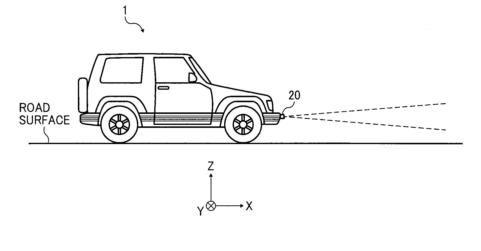
  • Optical scanner, object detector, and sensing apparatus
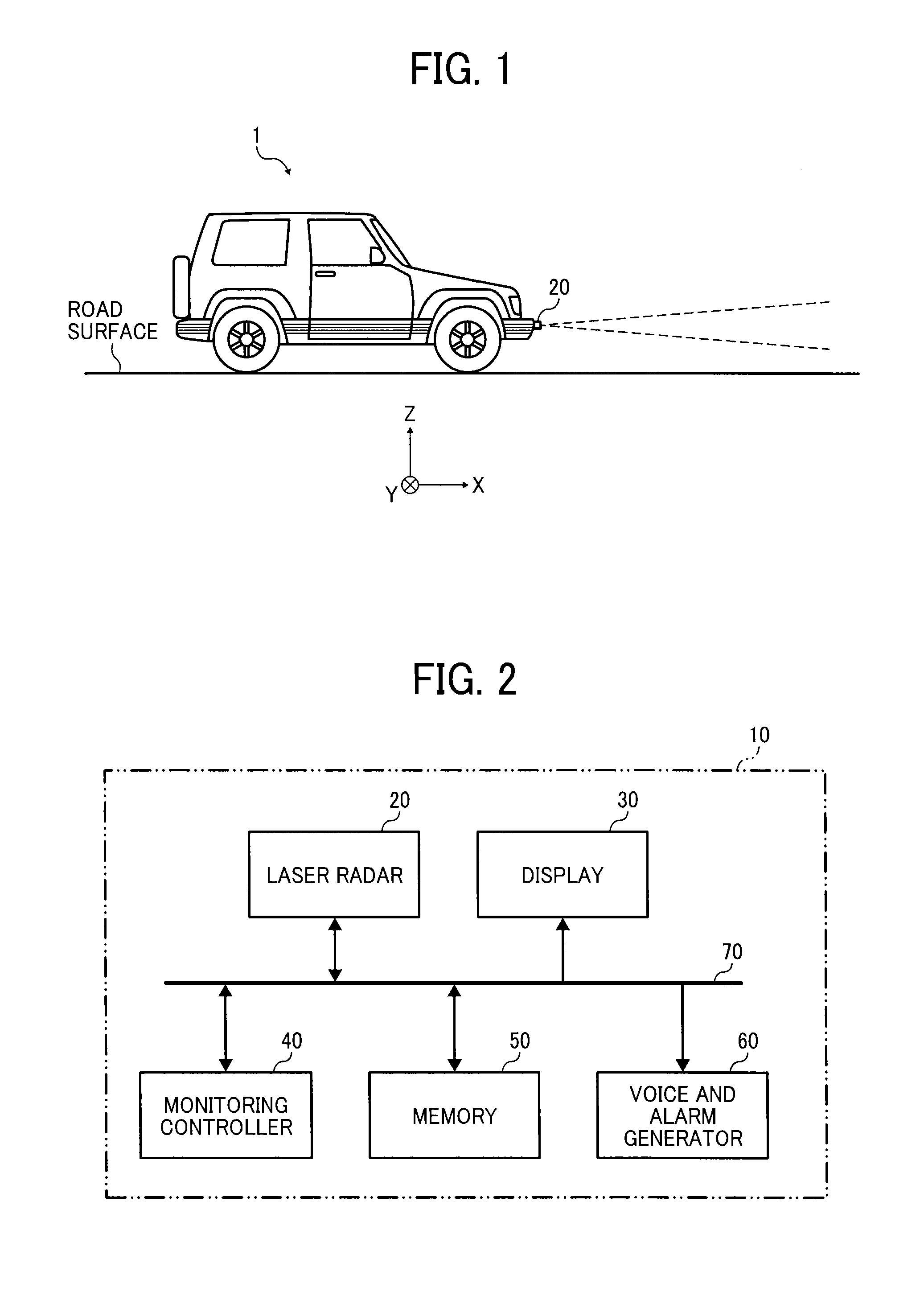
  • Optical scanner, object detector, and sensing apparatus
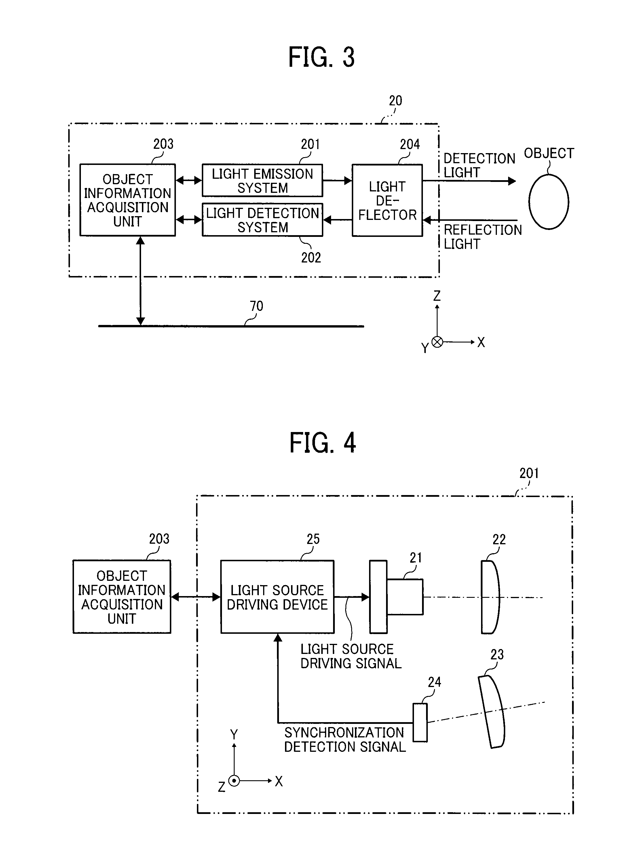
  • Optical scanner, object detector, and sensing apparatus

Examples


Embodiment Construction

[0041]The terminology used herein is for the purpose of describing particular embodiments only and is not intended to be limiting of the present invention. As used herein, the singular forms “a”, “an” and “the” are intended to include the plural forms as well, unless the context clearly indicates otherwise. It will be further understood that the terms “includes” and / or “including”, when used in this specification, specify the presence of stated features, integers, steps, operations, elements, and / or components, but do not preclude the presence or addition of one or more other features, integers, steps, operations, elements, components, and / or groups thereof.

[0042]In describing embodiments shown in the drawings, specific terminology is employed for the sake of clarity. However, the present disclosure is not intended to be limited to the specific terminology so selected and it is to be understood that each specific element includes all technical equivalents that have the same structur...


PUM


Abstract

An optical scanner is provided including a light source configured to emit light, a light source driving device configured to drive the light source, a light deflector having at least one rotating reflection plane and configured to deflect the light emitted from the light source to a scanning area, and a light detector configured to output a signal to control a timing at which scanning of the scanning area by the light deflected by the light deflector starts, where the light detector and the scanning area are sequentially scanned in a single scanning by one reflection plane of the light deflector, and the light source driving device drives the light source using a first driving method when the light scans the light detector, and drives the light source using a second driving method that is different from the first driving method when the light scans the scanning area.

Description

CROSS-REFERENCE TO RELATED APPLICATION[0001]This patent application is based on and claims priority pursuant to 35 U.S.C. §119(a) to Japanese Patent Application No. 2014-173593, filed on Aug. 28, 2014, in the Japan Patent Office, the entire disclosure of which is hereby incorporated by reference herein.BACKGROUND[0002]1. Technical Field[0003]Embodiments of the present invention relate to an optical scanner, an object detector, and a sensing apparatus.[0004]2. Background Art[0005]Currently, object detectors that detect the presence of an object or the distance to the object are being developed.[0006]Moreover, optical scanners that detect the scanning position of a light beam with high accuracy are known.[0007]However, it has proven difficult for conventional devices to combine compactness and good detection accuracy.SUMMARY[0008]Embodiments of the present invention described herein provide an optical scanner including a light source configured to emit light, a light source driving de...

Claims


Application Information

Patent Timeline
IPC IPC(8): G01S17/931G01S17/06G01S17/10G01S17/58
CPCG01S17/936G01S17/06G01S17/58G01S17/10G01S17/42G01S7/4817G01S7/484G01S17/931
Inventor IMAI, SHIGEAKIUEHIRA, MASATAKASAKAI, KOHJINAKAMURA, TADASHIITAMI, YUKIO
Owner RICOH KK
Features
  • Generate Ideas
  • Intellectual Property
  • Life Sciences
  • Materials
  • Tech Scout
  • Unparalleled Data Quality
  • Higher Quality Content
  • 60% Fewer Hallucinations
Learn More