Device and method for displaying an image

a projector and image technology, applied in the field of image projecting devices, can solve the problems of difficult to determine the exact position of the projector, the angle of the object is not uniform, and the projector cannot precisely determine the effect, and achieve the effect of high operability

Inactive Publication Date: 2010-10-07
FUNAI ELECTRIC CO LTD
View PDF12 Cites 19 Cited by
  • Summary
  • Abstract
  • Description
  • Claims
  • Application Information

AI Technical Summary

Benefits of technology

[0014]The invention has been made for overcoming the above problems, and an object of the inve

Problems solved by technology

This is due to the facts that the light scattered by the object diverges, and that the angle of the object is not uniform.
Therefore, it is difficult in this type of projector to determine whether a click operation is performed on an imaginary input plane or not.
This is because the projector can

Method used


Image

  • Device and method for displaying an image
  • Device and method for displaying an image
  • Device and method for displaying an image

Examples


first embodiment

[0036]

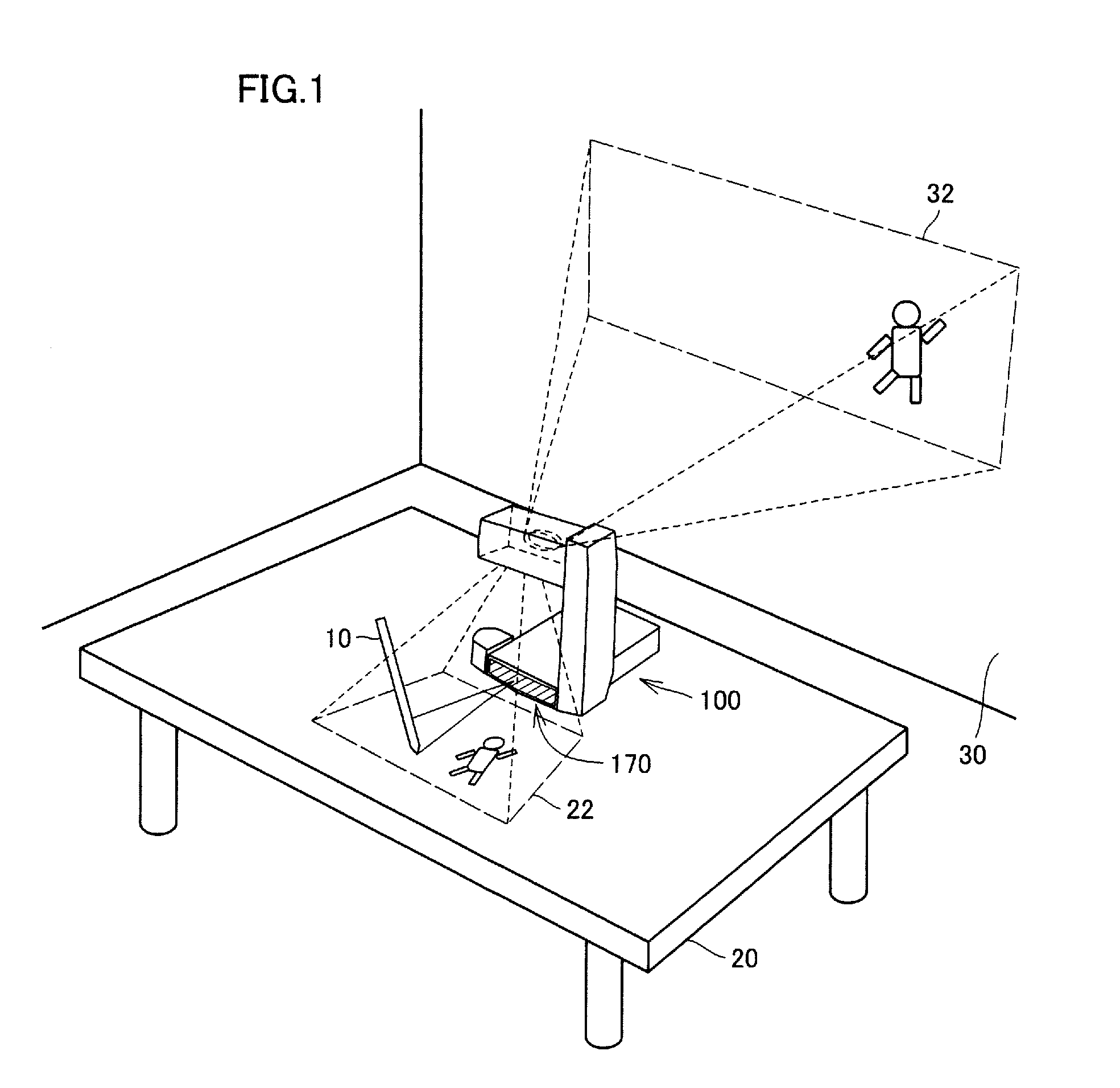
[0037]Referring to FIG. 1, description will be given on a form of use of a projector 100 according to an embodiment of the invention.

[0038]Projector 100 is used on a desk 20. Projector 100 projects a VUI (Virtual User Interface) screen picture 22 in a first direction. Also, projector 100 projects a main projection screen picture 32 in a second direction different from the first direction.

[0039]Main projection screen picture 32 is usually projected such that many persons can see it. In FIG. 1, projector 100 projects main projection screen picture 32 onto a wall 30. However, wall 30 is merely an example of a projection target plane onto which main projection screen picture 32 is projected. Wall 30 may be replaced with a screen member or the like.

[0040]VUI screen picture 22 is a screen picture to be referred to by the user. VUI screen picture 22 is usually projected near projector 100. In FIG. 1, projector 100 projects VUI screen picture 22 onto desk 20.

[0041]Projector 100 splits...

second embodiment

[0194]

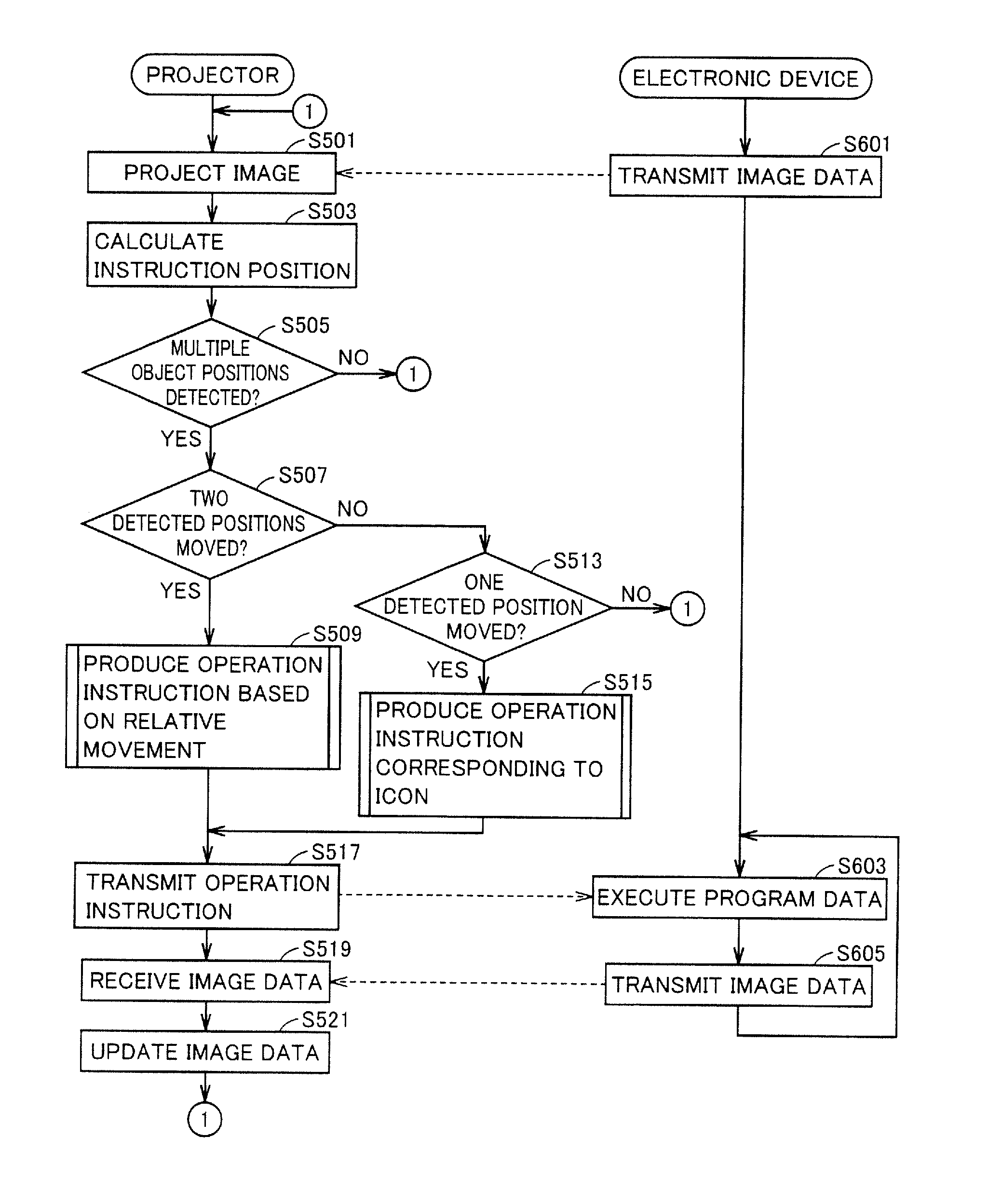
[0195]Projector 100 according to the first embodiment produces image data 472 by CPU 140 (or image processing unit 495) in projector 100. More specifically, projector 100 executes the program stored in projector 100 to produce image data 472.

[0196]For example, in the first embodiment, projector 100 can produce image data 472 for projection based on the externally accepted image data. For example, therefore, projector 100 can perform slide-show display of the plurality of images in a storage medium (SD, flash memory or the like) mounted on projector 100.

[0197]Conversely, a projector 100# according to the second embodiment does not produce image data 472 by itself. For using projector 100#, it is connected to an external electronic device 1000. According to the operation on the VUI screen picture, projector 100# instructs the change in image data 472 to be transmitted from electronic device 1000 to projector 100#. In the second embodiment, electronic device 1000 plays an importa...


PUM


Abstract

A projector producing an imaginary input plane with high operability is provided. A projector according to an embodiment projects a VUI screen picture onto a desk, and projects a main projection screen picture to a wall. The projector includes a light receiving element. The light receiving element is arranged in a position where light emitted toward the desk (VUI screen picture) and reflected (or scattered) by an object near the desk enters. The projector calculates a position of the object based on light sensing timing by the light receiving element and light scan positions at various points in time. The projector changes a projected screen picture when it determines that object is simultaneously in contact with a plurality of portions of the VUI screen picture and at least one of contact positions moves.

Description

BACKGROUND OF THE INVENTION[0001]1. Field of the Invention[0002]The present invention relates to a technique for projecting an image. Particularly, the invention relates to a device and a method for projecting an image with laser light.[0003]2. Description of the Background Art[0004]Projectors that project an image onto a projection target plane such as a wall are presently used in many places. In recent years, various kinds of projectors have been under development.[0005]An imaginary keyboard is one of uses of the projector. For example, National Publication No. 2004-523031 has disclosed a data input device that can be used as an imaginary keyboard. This data input device includes an illumination device emitting light to an engagement plane, a sensor sensing the light that is emitted by the illumination device and is scattered by engagement of an object with an engagement plane, and a processor receiving an output of the sensor and providing data entry input to a service circuit.[0...

Claims


Application Information

Patent Timeline
IPC IPC(8): G09G5/00
CPCG06F3/0423H04N9/3129H04N9/3147H04N9/3194
Inventor NISHIGAKI, HIROSHIHIRANO, ATSUYACHIKAOKA, ATSUHIKONISHIOKA, KEN
Owner FUNAI ELECTRIC CO LTD
Why Eureka
Try Eureka