
Two-dimensional scanning apparatus and scanning type image displaying apparatus using the same

a two-dimensional scanning and scanning type technology, applied in the direction of color television details, picture reproducers using projection devices, instruments, etc., can solve the problems of deteriorating the dignity of the image, not at all correcting the tv distortion,

Inactive Publication Date: 2005-09-01
CANON KK
View PDF10 Cites 22 Cited by
  • Summary
  • Abstract
  • Description
  • Claims
  • Application Information

AI Technical Summary

Benefits of technology

[0009] It is an object of the present invention to provide a two-dimensional scanning apparatus which can well correct TV distortion caused by a beam being two-dimensionally deflected by deflecting means and trapezoid distortion caused by an image being obliquely projected onto a surface to be scanned. It is a further object of the present invention to provide a two-dimensional scanning apparatus in which a scanning optical system can be downsized and chromatic aberration does not occur, and a scanning type image displaying apparatus using the same.
[0043] In the above-described optical scanning apparatus, it is preferable that the aforementioned at least one reflecting surface of a non-rotation symmetrical shape be formed so that along the direction of a line of intersection between a plane including an optical path of the optical paths of the principal ray which is incident on the reflecting surface and an optical path emergent from the reflecting surface and the reflecting surface, optical power in a plane perpendicular to the line of intersection may gradually become great.

Problems solved by technology

H11-084291 and Japanese Patent Application Laid-open No. 2001-281583 does not at all correct TV distortion.
Further, when an image has been obliquely projected onto a surface to be scanned such as a screen, trapezoid distortion has occurred to thereby deteriorate the dignity of the image, the two-dimensional scanning apparatus disclosed in Japanese Patent Application Laid-Open No.

Method used


Image

  • Two-dimensional scanning apparatus and scanning type image displaying apparatus using the same
  • Two-dimensional scanning apparatus and scanning type image displaying apparatus using the same
  • Two-dimensional scanning apparatus and scanning type image displaying apparatus using the same

Examples


first embodiment

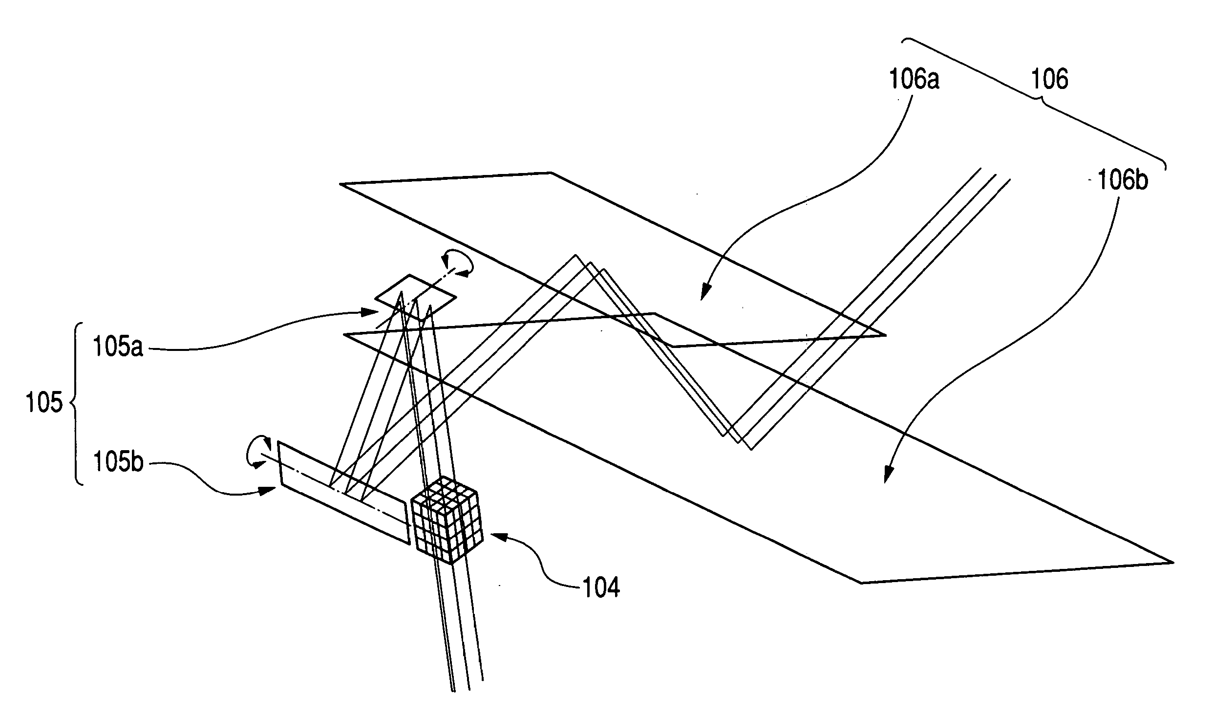
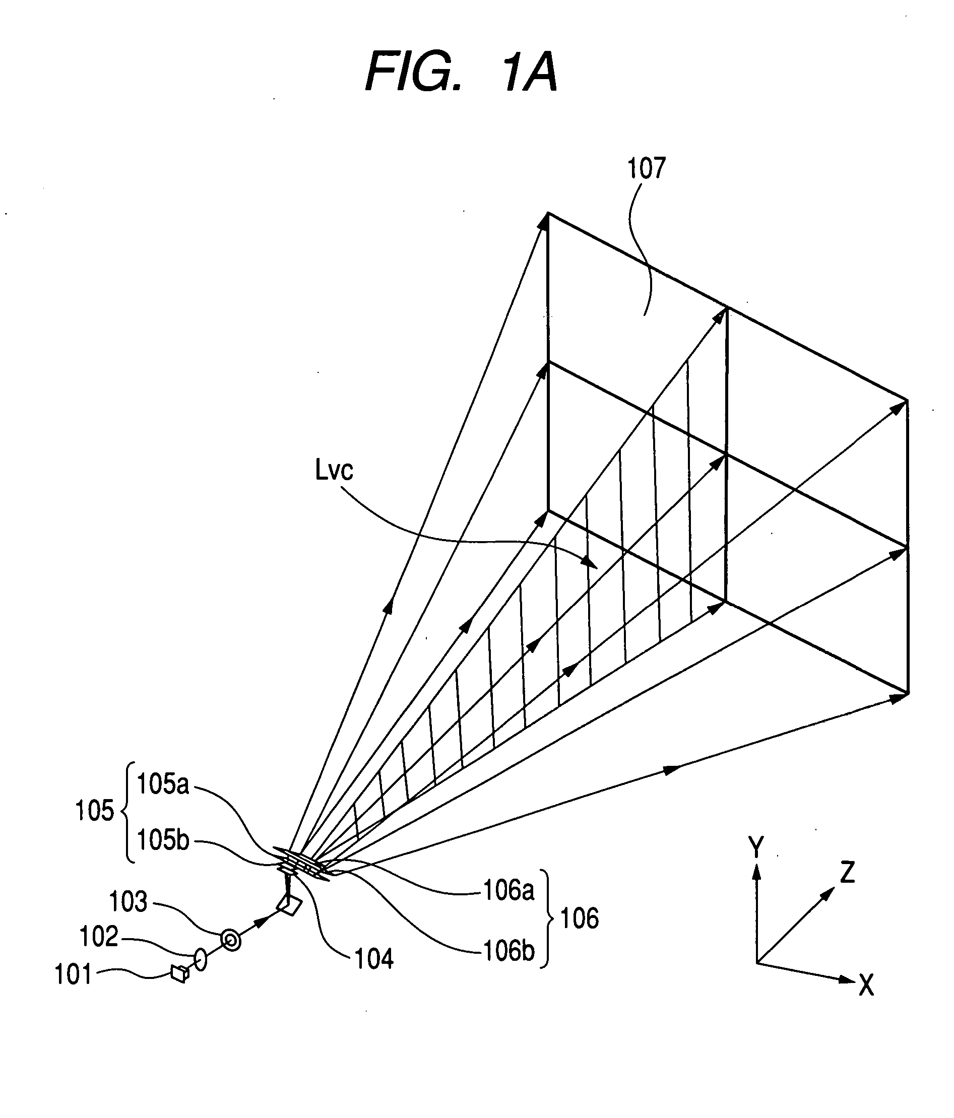
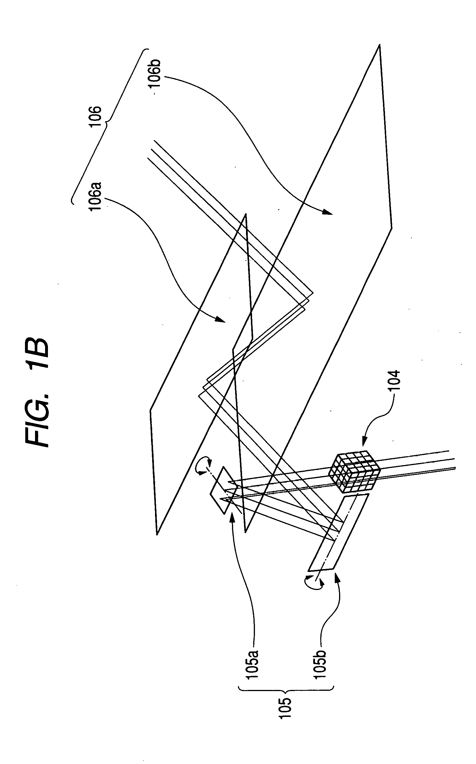
[0095]FIG. 1 is a perspective view of the essential portions of a two-dimensional scanning apparatus according to First Embodiment of the present invention, FIG. 2A is a cross-sectional view (horizontal scanning sectional view, or XZ cross section) of the essential portions of First Embodiment of the present invention in a horizontal scanning direction, and FIG. 2B is a cross-sectional view (vertical scanning sectional view, or YZ cross section) of the essential portions of First Embodiment of the present invention in a vertical scanning direction.

[0096] In these figures, the reference numeral 101 designates light source means having a semiconductor laser capable of effecting light modulation (which need not be a semiconductor laser if it is a light emitting element), for example, a red semiconductor laser (or a green semiconductor laser, or a blue semiconductor laser or a semiconductor laser emitting light of other color within a visible light area). However, a red semiconductor l...

second embodiment

[0217]FIG. 14A is a horizontal scanning sectional view of Second Embodiment of the present invention, and FIG. 14B is a vertical scanning sectional view of Second Embodiment of the present invention. In FIGS. 14A and 14B, the same elements as the elements shown in FIGS. 2A and 2B are given the same reference characters.

[0218] The differences of the present embodiment from the aforedescribed First Embodiment are that light source means 201 are constituted by three light sources (semiconductor lasers) 201a, 201b and 201c emitting beams of different wavelengths, and that two-dimensional deflecting means is constituted by a single deflector 205 having a reflecting surface and capable of resonating in a two-dimensional direction. In the other points, the construction and optical action of the present embodiment are substantially similar to those of the First Embodiment, whereby a similar effect is obtained.

[0219] That is, in FIGS. 14A and 14B, the reference numeral 201 designates light...

third embodiment

[0258]FIG. 21 is a perspective view of the essential portions of a two-dimensional scanning apparatus according to Third Embodiment of the present invention. FIG. 22A is a horizontal scanning sectional view of the two-dimensional scanning apparatus according to the Third Embodiment of the present invention, and FIG. 22B is a vertical scanning sectional view of the two-dimensional scanning apparatus according to The Third Embodiment of the present invention. In FIGS. 21, 22A and 22B, the same elements as the elements shown in FIGS. 2A and 2B are given the same reference characters.

[0259] The difference of the present embodiment from the aforedescribed First Embodiment is that the scanning optical system is constituted by a single prism 306 including at least two reflecting surfaces of a non-rotation symmetrical shape. In the other points, the construction and optical action of the present embodiment are substantially similar to those of First Embodiment, whereby a similar effect is ...


PUM


Abstract

The optical scanning apparatus of the present invention is an optical scanning apparatus for scanning a surface to be scanned with light from a light source, provided with a deflecting optical system for deflecting a beam from a light source optical system in a first scanning direction and a second scanning direction orthogonal to the first scanning direction, and a scanning optical system including at least one reflecting surface of a non-rotation symmetrical shape, and for directing the deflected beam deflected by the deflecting optical system onto the surface to be scanned by the use of the aforementioned at least one reflecting surface of a non-rotation symmetrical shape, wherein the principal ray of the beam incident on the center of the angle of view of the surface to be scanned is incident while being inclined with respect to the surface to be scanned in at least the first scanning direction of the first and second scanning directions.

Description

BACKGROUND OF THE INVENTION [0001] 1. Field of the Invention [0002] This invention relates to a two-dimensional scanning apparatus and a scanning type image displaying apparatus using the same, and particularly is adapted to two-dimensionally scan a beam (deflected beam) deflected by deflecting means to thereby project and display a two-dimensional image on a surface to be scanned (a screen surface). [0003] 2. Related Background Art [0004] There have been proposed various two-dimensional scanning apparatuses which two-dimensionally deflect a beam emitted from light source means by deflecting means, two-dimensionally optically scan on a surface to be scanned by a spot, and form a two-dimensional image by the afterimage effect thereof (see, for example, Japanese Patent Application Laid-open No. H11-084291 and Japanese Patent Application Laid-open No. 2001-281583). [0005] Now, it is known that by a beam being two-dimensionally deflected and scanned, so-called distortion occurs to a two...

Claims


Application Information

Patent Timeline
IPC IPC(8): G02B26/10H04N9/31
CPCG02B26/101H04N9/3129G02B26/105
Inventor ISHIHARA, KEIICHIRO
Owner CANON KK
Learn More