Illumination device, projection type image display device, and optical device

a projection type, image display technology, applied in the direction of instruments, lighting and heating apparatus, lenses, etc., can solve the problems of affecting the effect of coherent light, the inability to remove the speckle noise generated on the screen, etc., and achieve the effect of suppressing the speckle generated on the screen

Active Publication Date: 2014-05-01
DAI NIPPON PRINTING CO LTD
View PDF3 Cites 19 Cited by
  • Summary
  • Abstract
  • Description
  • Claims
  • Application Information

AI Technical Summary

Benefits of technology

[0026]According to the illumination device of the present invention, the optical scanning section scans the coherent light to cause the illumination light to be emitted from the lens array to illuminate the area to be illuminated at an angle changing with time. This allows the speckle generated in the area to be illuminated to be made invisible to a viewer. Moreover, in the projection type image display device according to the present invention, the screen is also subjected to irradiation at an angle changing with time, thereby effectively suppressing the speckle to be generated on the screen.
[0027]Moreover, in the illumination device (projection type image display device) according to the present invention, it is possible to illuminate the area to be illuminated (image formation area) with the diverging light which is emitted from the lens array and whose diverging angle has been controlled. This allows respective sections of the area to be illuminated (image formation area) to be illuminated under substantially the same conditions, which, for example, allows the entire area to be illuminated (image formation area) to be illuminated uniformly.

Problems solved by technology

However, since an angle of incident light from a diffusion center to the screen is invariant at any point on the screen, so that light scattering characteristics at respective points on the screen are constant, with the result that removal effect of the speckle noise generated on the screen can hardly be obtained.
Such speckle caused by the coherent light has become a problem not only in a projection type image display device (projector) that uses the coherent light as a light source, but also in various illumination devices that use the coherent light.

Method used


Image

  • Illumination device, projection type image display device, and optical device
  • Illumination device, projection type image display device, and optical device
  • Illumination device, projection type image display device, and optical device

Examples


Embodiment Construction

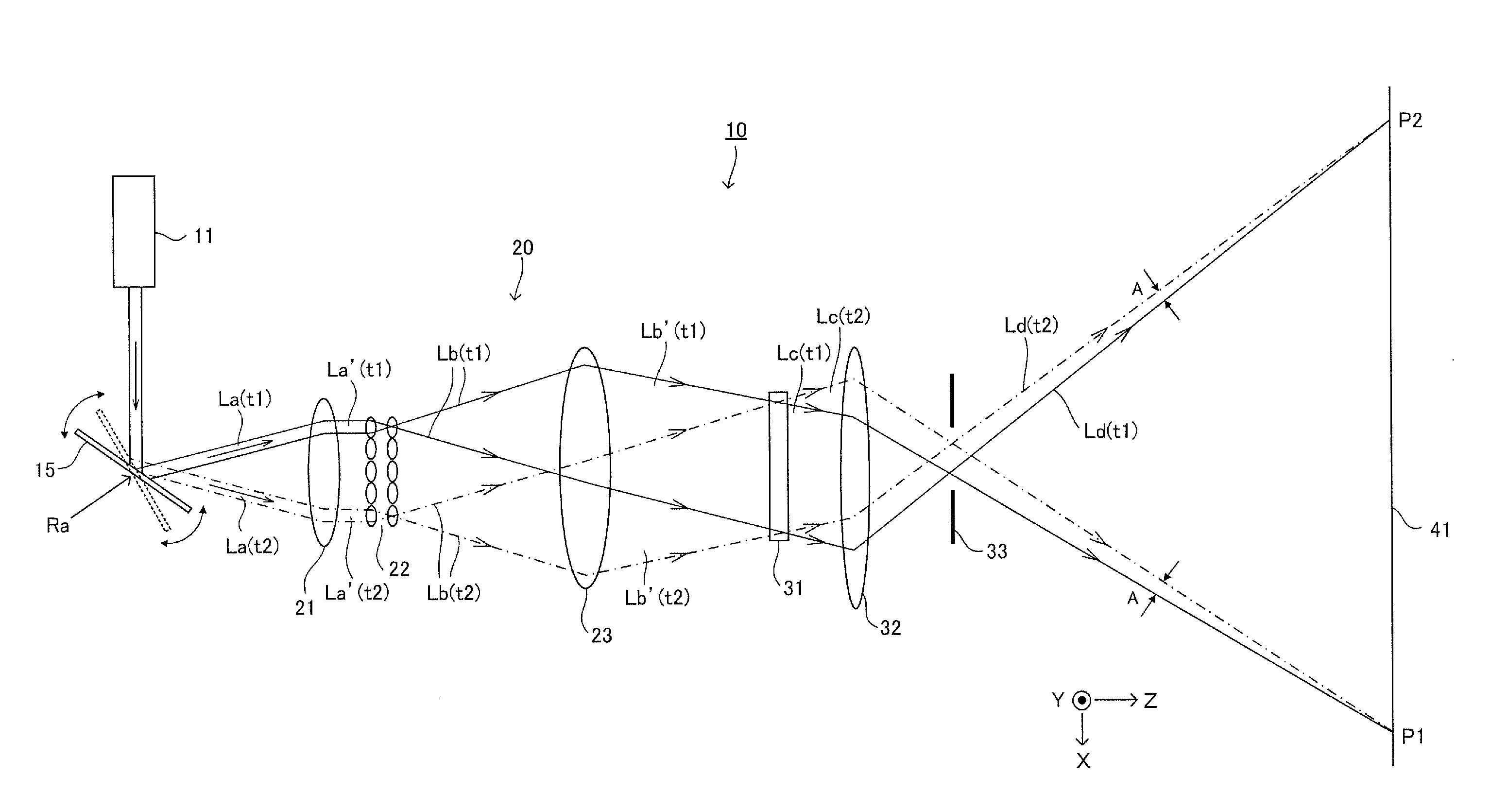
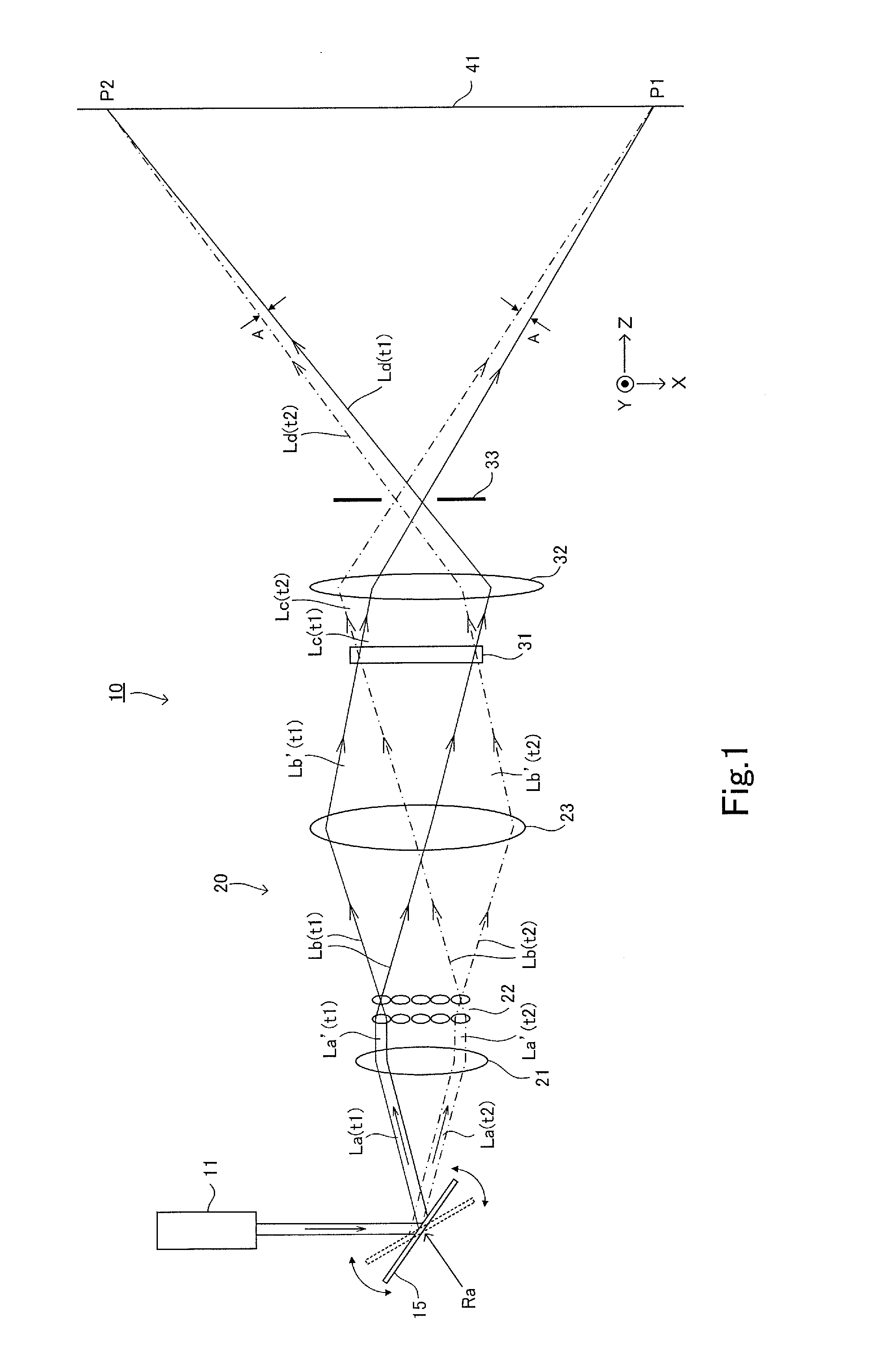
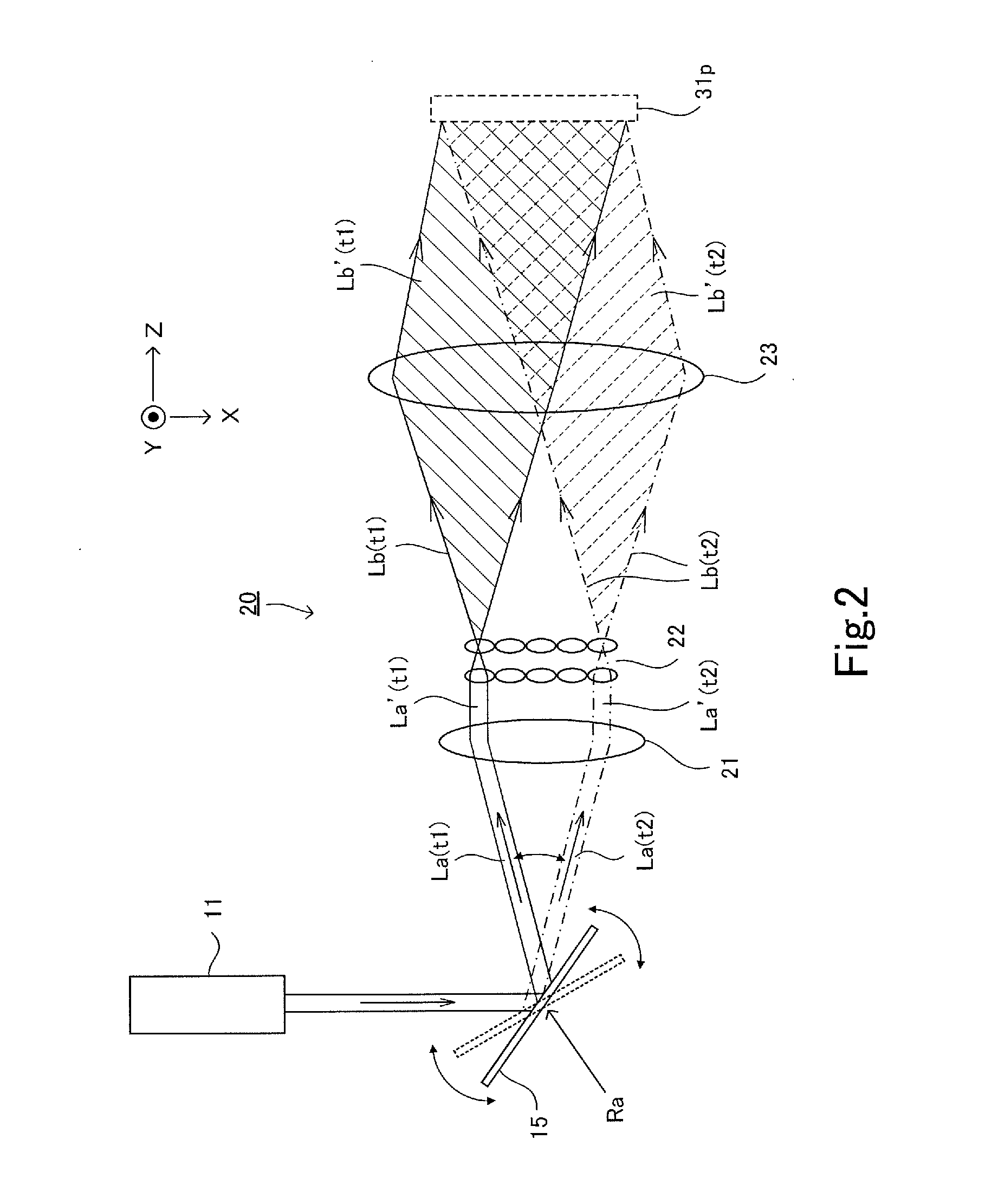
[0036]Now, an illumination device and a projection type image display device according to an embodiment of the present invention will be described with reference to the drawings. FIG. 1 is a view illustrating a configuration of a projection type image display device provided with an illumination device according to an embodiment of the present invention. It should be noted that drawings described hereinafter are each a schematic diagram, and may represent different shape, dimension, and position from those actually illustrated.

[0037]A projection type image display device 10 according to the present embodiment includes an illumination device 20, an optical modulation element 31 for forming an image, and a projection optical system 32 that projects an image formed by the optical modulation element 31 on a screen 41. In the drawings, a surface of the screen 41 on which an image is projected is assumed to be X-Y plane, and an axis normal to the X-Y plane is assumed to be a Z-axis. As th...


PUM


Abstract

To provide an illumination device and a projection type image display device that illuminate an area to be illuminated (image formation area) under conditions where speckle noise is less noticeable.
An illumination device according to the present invention includes: a light source 11 that emits coherent light; an optical scanning section 15 that scans the coherent light emitted from the light source 11; a lens array 22 including a plurality of element lenses and configured to diverge the light scanned by the optical scanning section; an optical path conversion system 23 configured to control a diverging angle of the diverging light to be emitted from respective points of the lens array 22 and to allow the diverging light whose diverging angle has been controlled to illuminate an area to be illuminated sequentially in an overlapping manner.

Description

TECHNICAL FIELD[0001]The present invention relates to an illumination device that uses coherent light such as laser light, a projection type image display device that uses the coherent light to illuminate an optical modulation element to project an image on a screen, and an optical device for use in the illumination device and projection type image display device.BACKGROUND ART[0002]There is known a projector (projection type image display device) that uses an optical modulation element (micro display) such as a liquid crystal or MEMS to visualize illumination light from a light source and projects an image based on the illumination light on a screen. Some of such projectors use, as its light source, a white light source such as a high-pressure mercury lamp and projects an image on a screen while magnifying an image obtained by illuminating a two-dimensional optical modulation element such as a liquid crystal.[0003]However, a high-intensity discharge lamp such as the high-pressure m...

Claims


Application Information

Patent Timeline
Patent Type & Authority Applications(United States)
IPC IPC(8): G02B27/48F21V9/14G03B21/14F21V5/00
CPCG02B27/48F21V5/008F21V9/14G03B21/14H04N9/3161G03B21/2033G03B21/2066G03B21/208G02B26/125G02B27/0927G02B27/0961H04N9/3129G02B27/286G02B3/0062G02B3/0087G02B26/105G02B26/12H04N9/3135
Inventor TANIGUCHI, YUKIOKURASHIGE, MAKIOOOYAGI, YASUYUKI
Owner DAI NIPPON PRINTING CO LTD
Why Eureka
Try Eureka