
Execution of sequential update

a technology of sequential update and sequential update, applied in the field of industrial design, can solve problems such as achieving a complex model

Active Publication Date: 2016-03-03
DASSAULT SYSTEMES
View PDF8 Cites 8 Cited by
  • Summary
  • Abstract
  • Description
  • Claims
  • Application Information

AI Technical Summary

Benefits of technology

The patent describes a computer-implemented method for designing a three-dimensional modeled object that represents an industrial product. The method involves creating a modeling graph with nodes and arcs that represent the geometrical objects and relationships linking them, including both procedural and live relationships. The modeling graph is then used to update the object when data is modified. The method can be used to design a wide range of industrial products, such as mechanical parts or consumer goods. The patent also provides a computer program and a computer system for implementing the method. The technical effects of the patent include improved efficiency and accuracy in designing complex industrial products.

Problems solved by technology

Indeed, using adequate procedures, one can achieve a complex model in relatively few operations.

Method used


Image

  • Execution of sequential update
  • Execution of sequential update
  • Execution of sequential update

Examples


Embodiment Construction

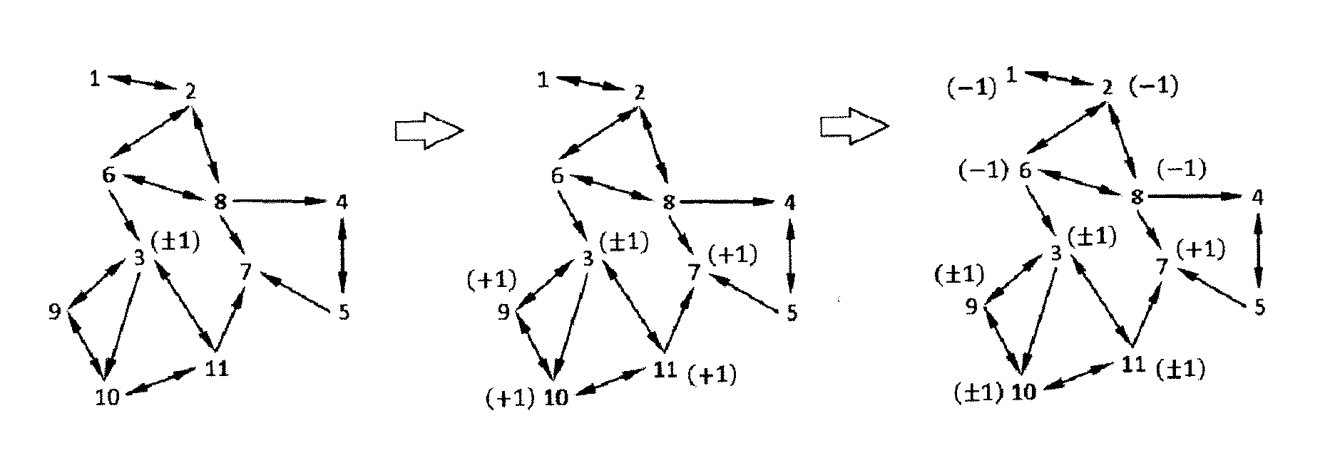
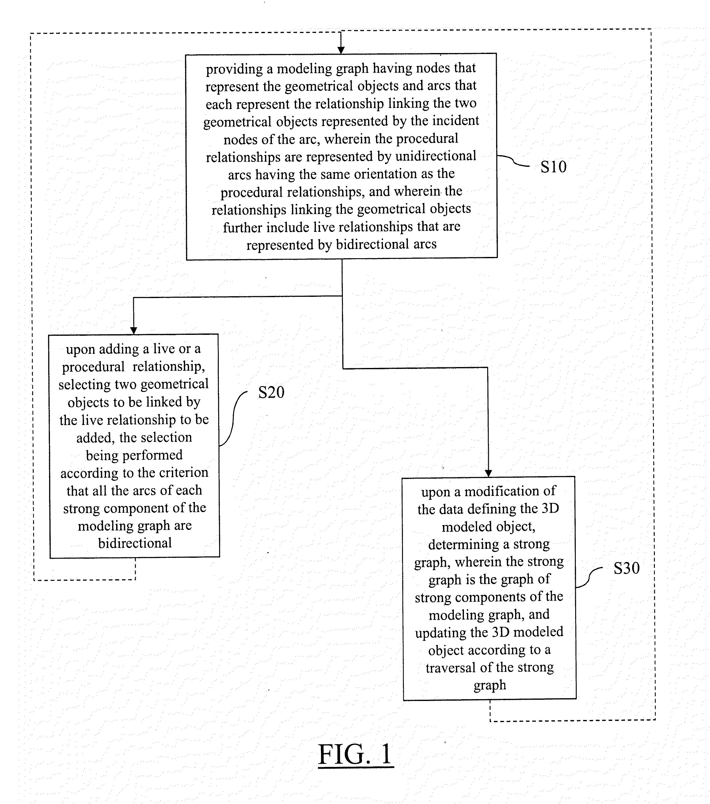
[0030]With reference to the flowchart of FIG. 1, it is proposed a computer-implemented method for designing a three-dimensional modeled object. The 3D modeled object represents an industrial product. The 3D modeled object is defined by data including a plurality of geometrical objects and relationships linking the geometrical objects. The relationships linking the geometrical objects include procedural relationships and live relationships. The method comprises a step of providing S10 a modeling graph having nodes that represent the geometrical objects and arcs that each represent the relationship linking the two geometrical objects represented by the incident nodes of the arc. In this graph, the procedural relationships are represented by unidirectional arcs having the same orientation as the procedural relationships, and the live relationships are represented by bidirectional arcs. The providing step S10 is represented distinctly from other steps of the method, but the providing ma...


PUM


Abstract

The invention notably relates to a computer-implemented method for designing a three-dimensional modeled object. The method comprises providing a modeling graph having nodes that represent geometrical objects and arcs that each represent a relationship linking the two geometrical objects represented by the incident nodes of the arc, wherein procedural relationships are represented by unidirectional arcs having the same orientation as the procedural relationships, and wherein the relationships linking the geometrical objects further include live relationships that are represented by bidirectional arcs. The method also comprises upon a modification of the data defining the 3D modeled object, determining a strong graph, wherein the strong graph is the graph of strong components of the modeling graph, and updating the 3D modeled object according to a traversal of the strong graph.Such a method improves the design of a 3D modeled object.

Description

CROSS-REFERENCE TO RELATED APPLICATIONS[0001]This application claims priority under 35 U.S.C. §119 or 365 to European Application No. 14306317.0, filed Aug. 26, 2014. The entire teachings of the above application(s) are incorporated herein by reference.FIELD OF THE INVENTION[0002]The invention notably relates to the field of industrial design, such as vehicle design, packaging design, mechanical design, consumer goods and electronics design.BACKGROUND[0003]A number of systems and programs are offered on the market for the design, the engineering and the manufacturing of objects. CAD is an acronym for Computer-Aided Design, e.g. it relates to software solutions for designing an object. CAE is an acronym for Computer-Aided Engineering, e.g. it relates to software solutions for simulating the physical behavior of a future product. CAM is an acronym for Computer-Aided Manufacturing, e.g. it relates to software solutions for defining manufacturing processes and operations. In such comput...

Claims


Application Information

Patent Timeline
Patent Type & Authority Applications(United States)
IPC IPC(8): G06T11/20G06F17/50G06T17/10
CPCG06F17/5086G06F17/50G06T17/10G06T11/206G06F30/00G06F30/10G06F30/17G06F30/12
Inventor RAMEAU, JEAN-FRANCOIS
Owner DASSAULT SYSTEMES
Learn More