Packet Delay Variation in a Packet Switched Network

a packet switched network and delay variation technology, applied in transmission systems, instruments, transmission systems, etc., can solve the problems of packets being sent back, parts of the jitter profile becoming constant latency, and tb>4/b>′ not reaching minimum latency, etc., and achieve the effect of large jitter values

Active Publication Date: 2016-03-03
CALNEX SOLUTIONS
View PDF7 Cites 4 Cited by
  • Summary
  • Abstract
  • Description
  • Claims
  • Application Information

AI Technical Summary

Benefits of technology

[0015]The invention provides a jitter test that involves determining whether it would be possible to delay an arriving packet accurately. If it is possible to do so, the delay is applied and then the test moves to the next delay in the test profile. This is achieved in practice by monitoring a period of time needed to send each packet, as well as the duration of the test profile delay and any delay applied to preceding packets. An advantage of doing this is that it allows relatively large jitter values to be applied in highly utilized (up to 100% bandwidth) networks.

Problems solved by technology

In these circumstances, the delayed packets are sent as soon as possible, but this can result in some packets being sent back to back.
In this case, t4′ does not achieve minimum latency.
Some parts of the jitter profile become constant latency.
As demonstrated above, the standard approaches to jitter test do not guarantee that all packets are delayed for the time defined in the test profile.
Instead packets are often delayed for longer.
This limits the accuracy of the test.

Method used


Image

  • Packet Delay Variation in a Packet Switched Network
  • Packet Delay Variation in a Packet Switched Network
  • Packet Delay Variation in a Packet Switched Network

Examples


Embodiment Construction

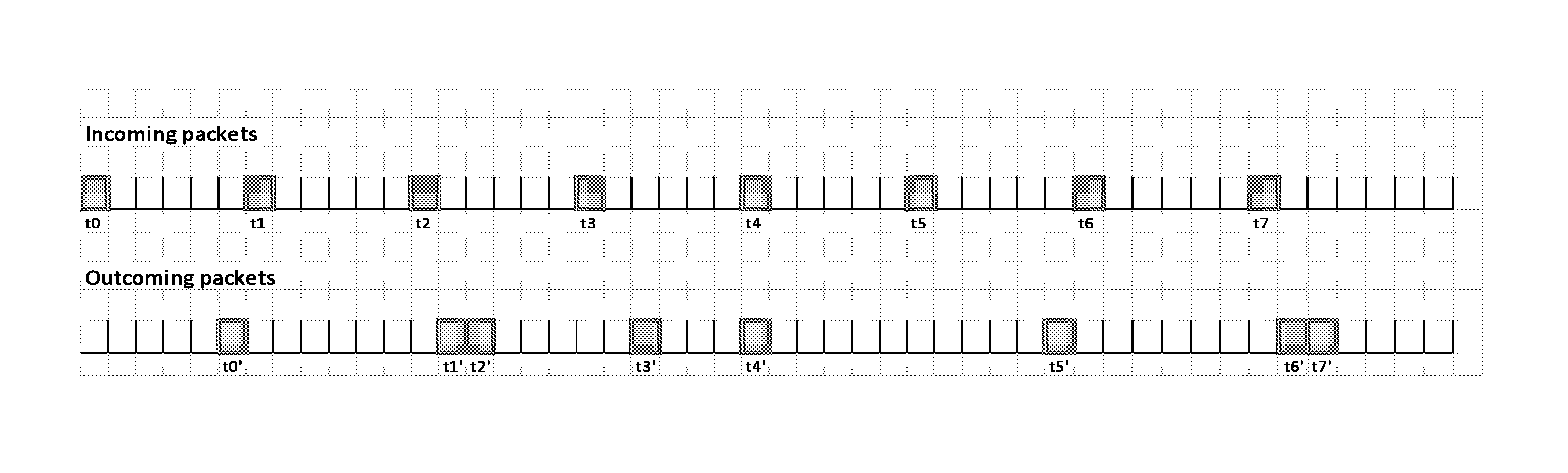
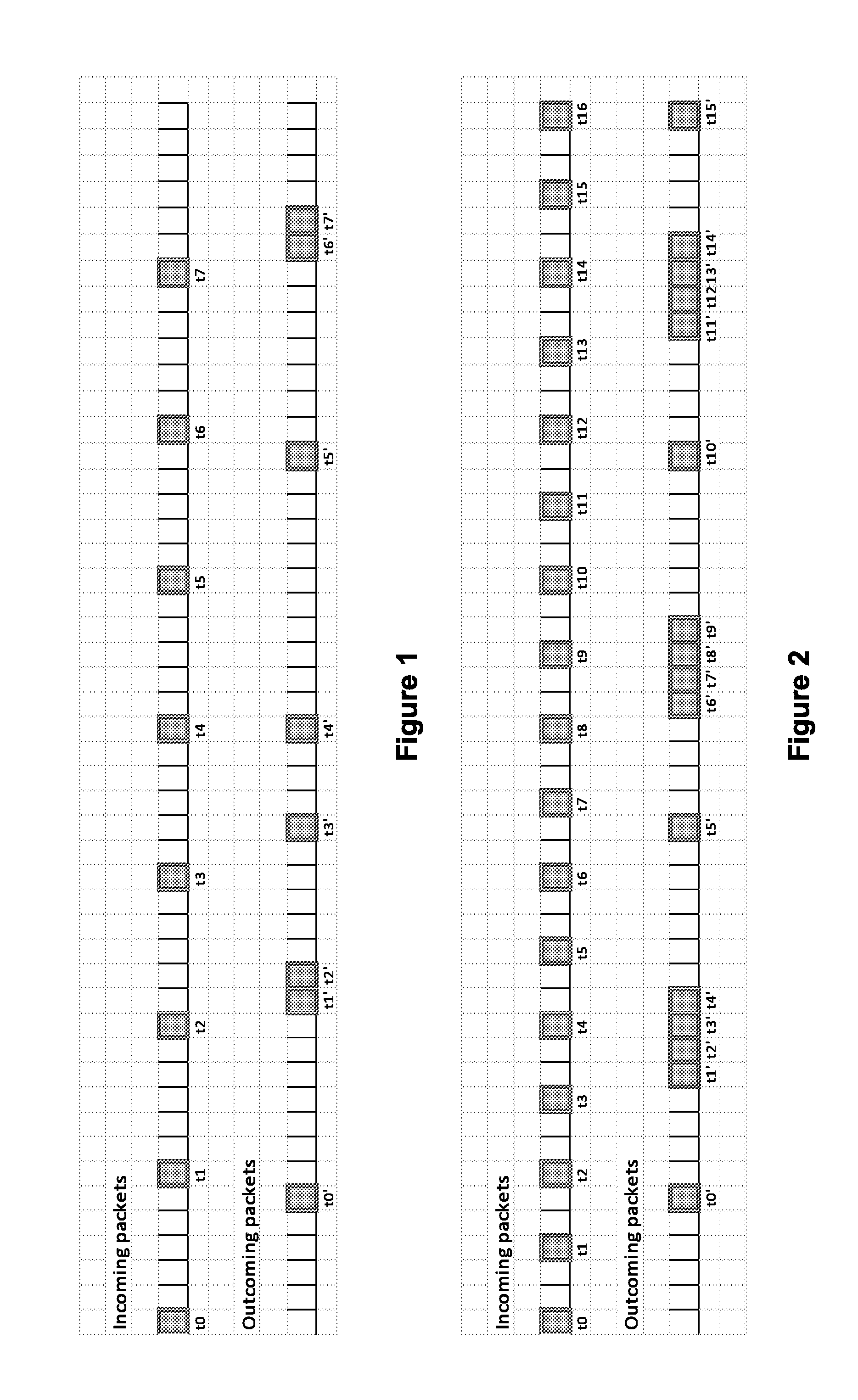
[0048]The present invention relates to a dynamic jitter tester and test method for generating packet delay variation by modifying a packet's timestamp with a delay value according to a test profile.

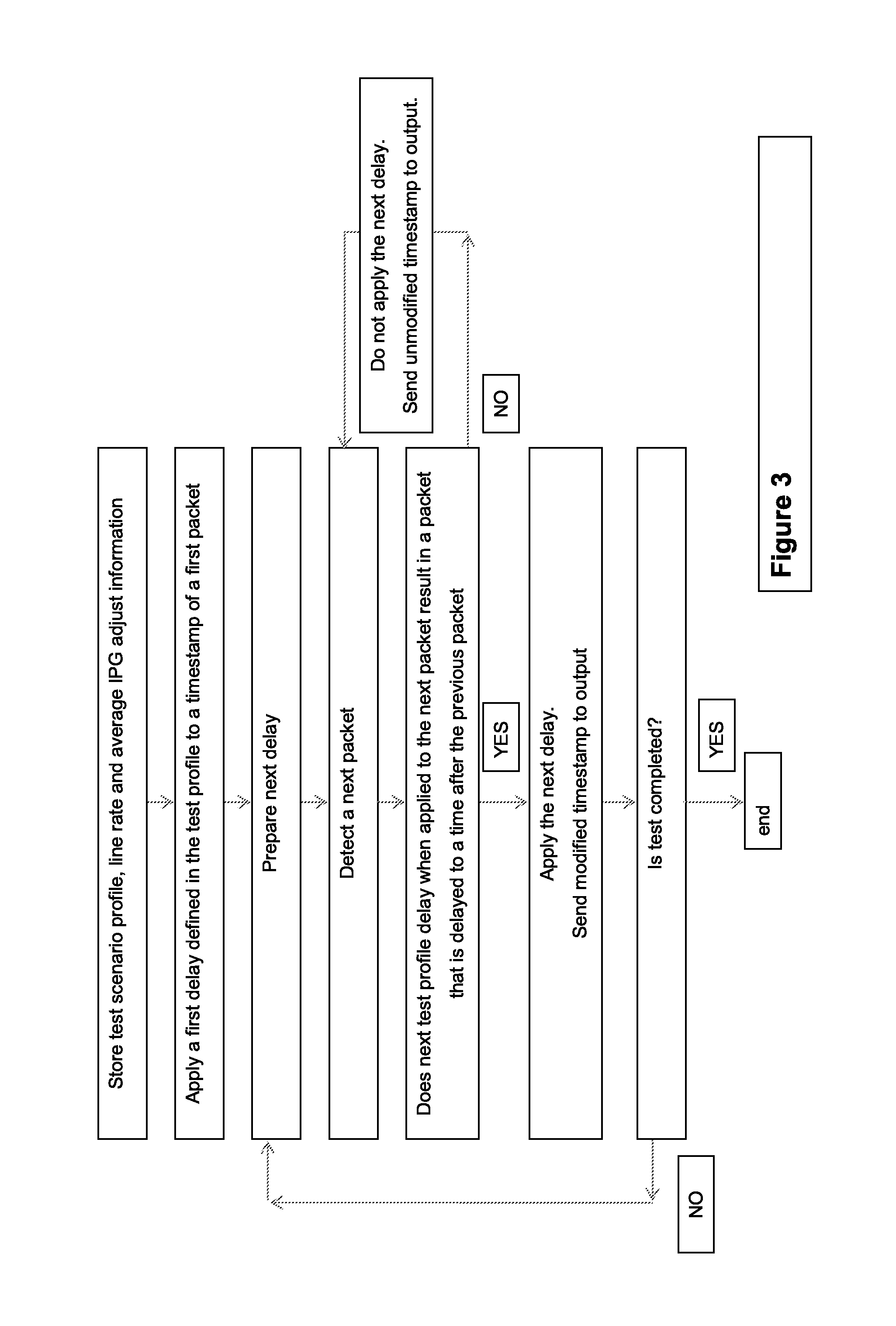
[0049]FIG. 3 shows steps of a first method for accurately implementing a jitter test. This involves applying a first delay defined in a test profile to a timestamp of a first packet; identifying a next delay defined in the test profile; and determining whether the next test profile delay when applied to the next packet would result in a packet that has a timestamp after the immediately preceding packet. If the answer to this is yes, then the next delay is applied. If the answer is no, then the delay in not applied and the packet timestamp is unmodified. This is continued until the next delay is applied. Then a subsequent delay in the test profile is identified and the process of determining whether the next delay can be applied is repeated until the test is completed.

[0050]In practice, pa...


PUM


Abstract

A packet switched network tester for testing a network using a packet delay variation test profile that has a plurality of different delays for applying to timestamps of packets received at the tester, the tester being configured to: detect a packet; determine whether a test profile delay when applied to the packet would result in a packet delayed to a time after any preceding packet; if not, repeat the steps of detecting and determining with subsequent packets; if yes, apply the delay to the timestamp of the packet and identify the next test profile delay; and repeat for the next test profile delay the steps of detecting and determining.

Description

CROSS REFERENCE TO RELATED APPLICATIONS[0001]This application claims priority to and the benefit of United Kingdom Patent Application Serial No. 1415332.4, filed Aug. 29, 2014, the contents of which as are hereby incorporated herein in their entirety by reference.BACKGROUND[0002]The present invention relates to packet switched network in-line tester and test method. In particular, the invention relates to a tester that is configured to generate packet delay variation by modifying a packet's timestamp according to a test scenario.[0003]The performance of packet switched telecommunications networks has to be regularly tested. One way of doing this is to introduce known delay variations in a test scenario and monitor the network response. A standard approach to generating packet delay variation, also known as packet jitter, is based on modifying each packet's timestamp with a delay value according to a test profile. The test profile may be generated using a probability distribution, fo...

Claims


Application Information

Patent Timeline
Patent Type & Authority Applications(United States)
IPC IPC(8): H04L12/26
CPCH04L43/087H04L43/50H04L43/106
Inventor LECHTANSKI, MICHAL
Owner CALNEX SOLUTIONS
Why Eureka
Try Eureka