Margin registration of a scan line in an electrophotographic printer

Inactive Publication Date: 2005-06-23
LEXMARK INT INC
View PDF22 Cites 2 Cited by
  • Summary
  • Abstract
  • Description
  • Claims
  • Application Information

AI Technical Summary

Benefits of technology

[0011] An advantage of the present invention is that the laser beams of a multi-color electrophotographic machine can be registered to start each scan line at an appropriate place on each photoconductive drum.

Problems solved by technology

Any misalignment in the color planes results in print quality pr

Method used


Image

  • Margin registration of a scan line in an electrophotographic printer
  • Margin registration of a scan line in an electrophotographic printer
  • Margin registration of a scan line in an electrophotographic printer

Examples


Embodiment Construction

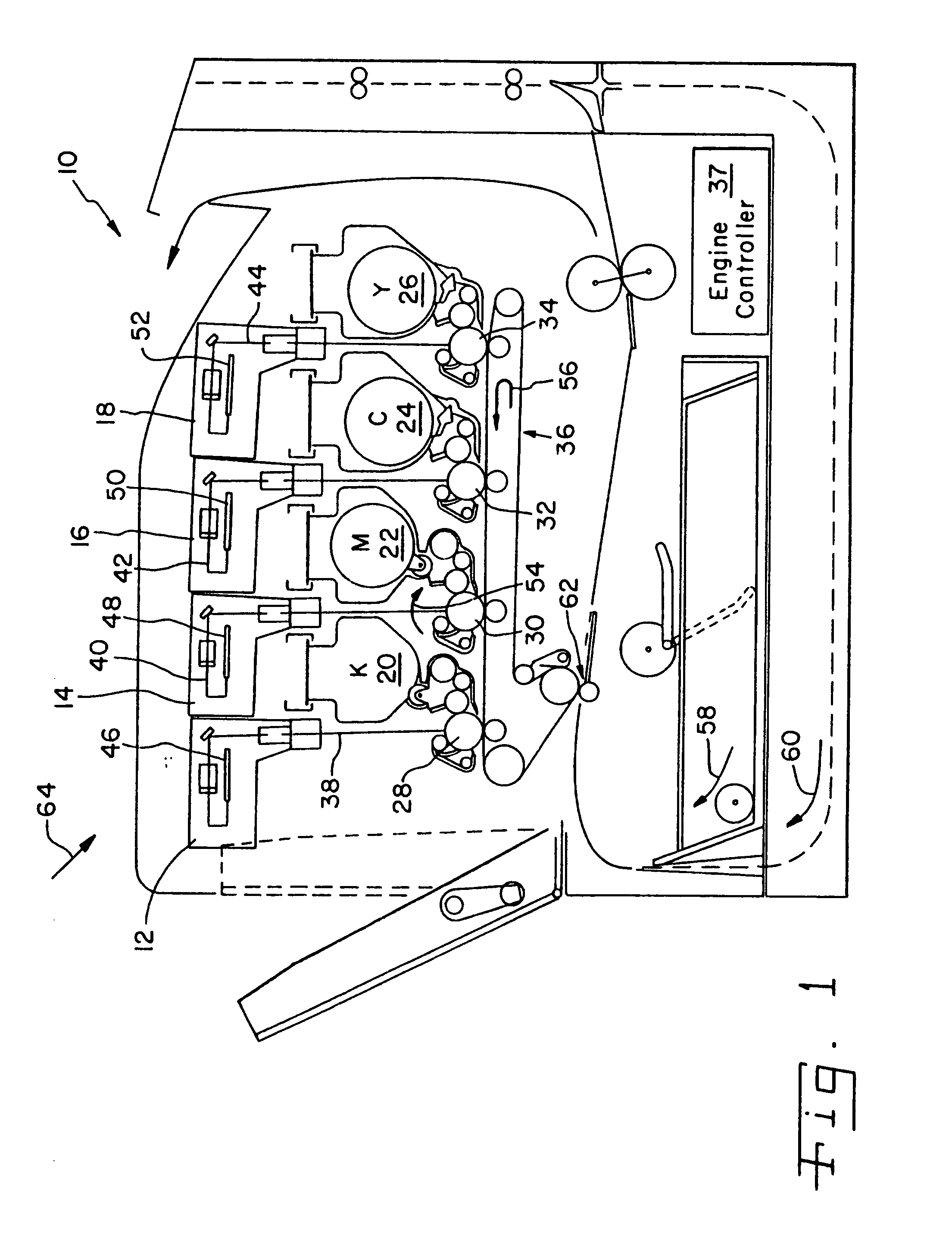
[0022] Referring now to the drawings and, more particularly, to FIG. 1, there is shown one embodiment of a multi-color laser printer 10 including laser printheads 12, 14, 16 and 18, a black toner cartridge 20, a magenta toner cartridge 22, a cyan toner cartridge 24, a yellow toner cartridge 26, photoconductive drums 28, 30, 32 and 34, an intermediate transfer member belt 36 and an engine controller 37.

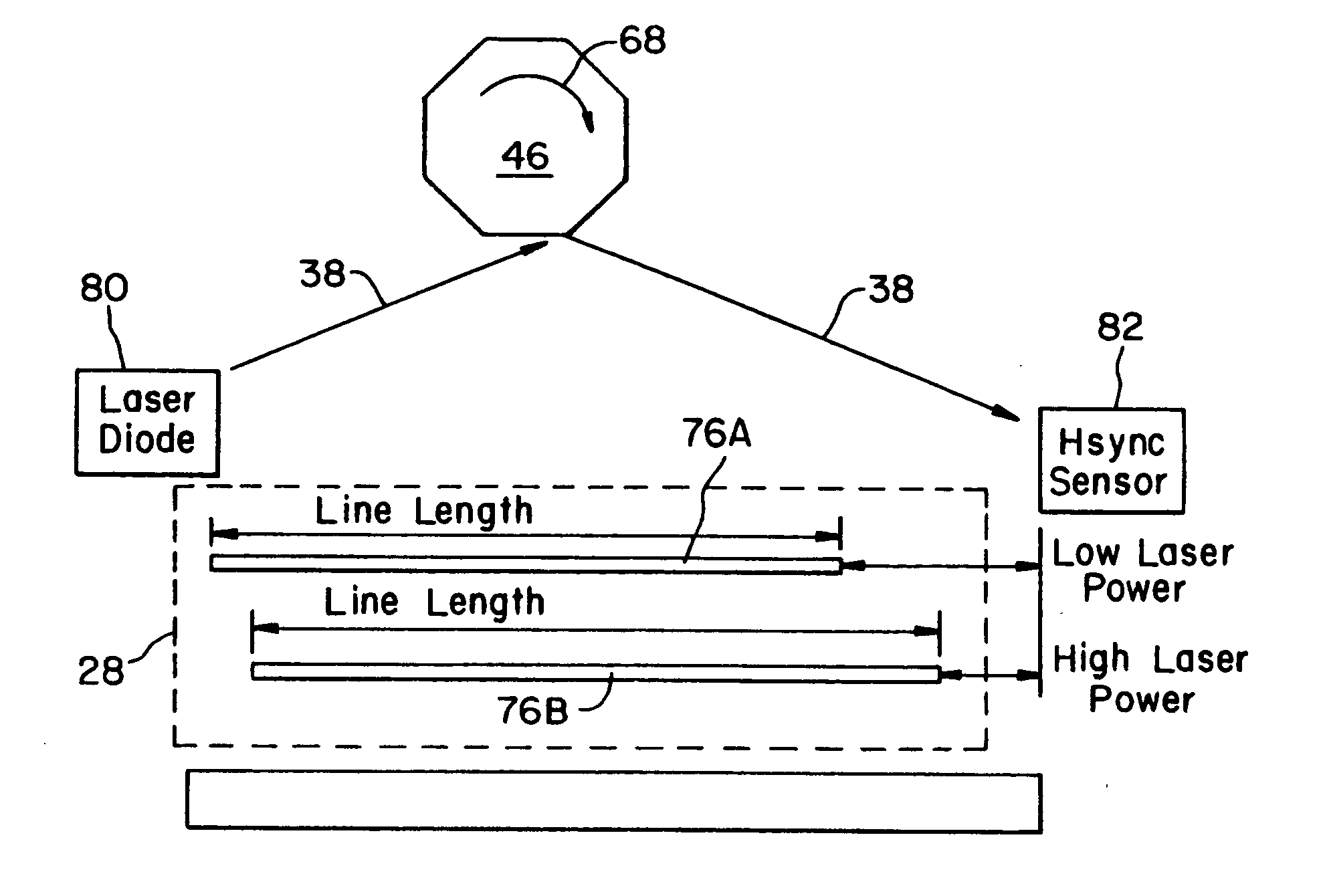
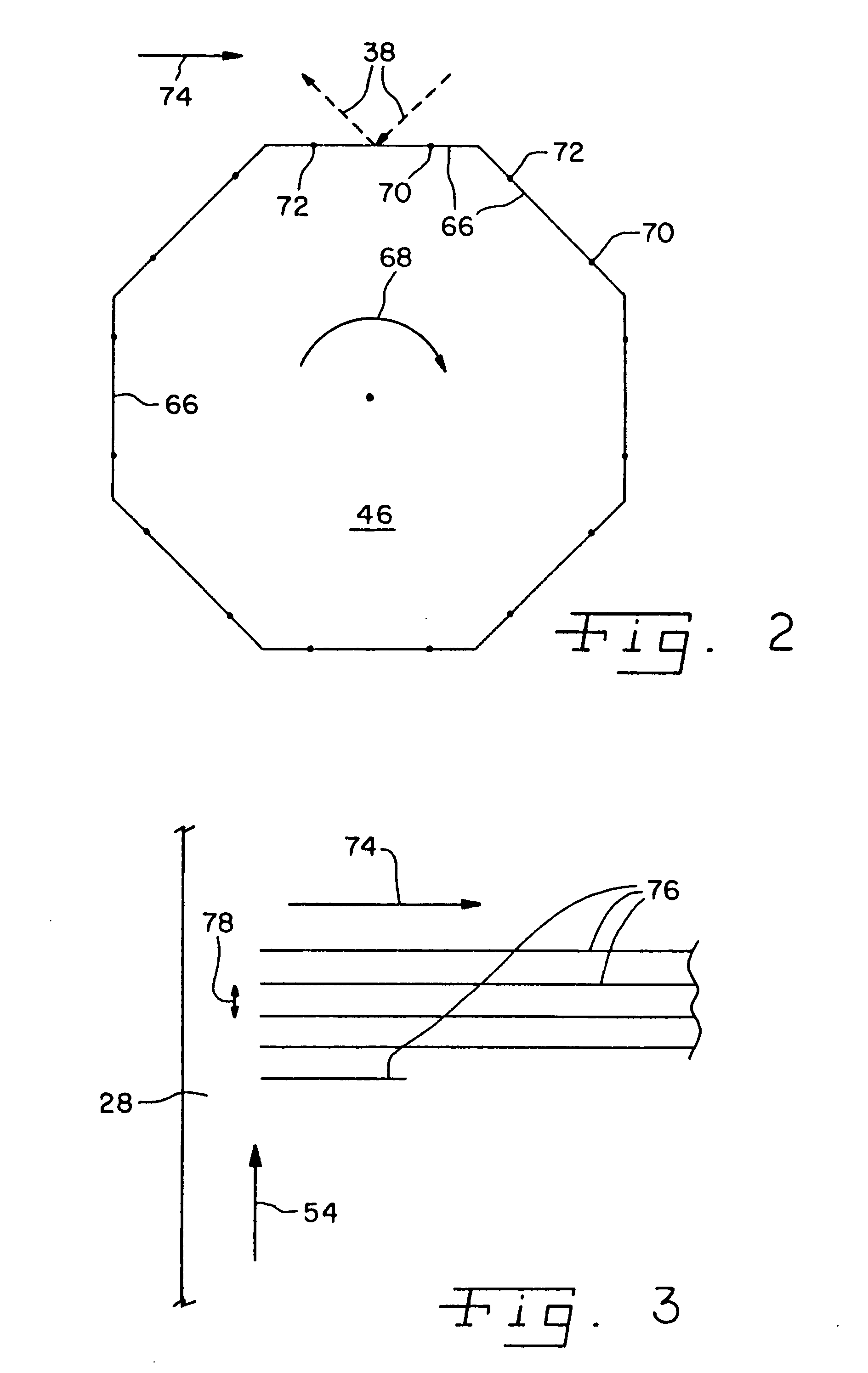
[0023] Each of laser printheads 12, 14, 16 and 18 project a respective laser beam 38, 40, 42 and 44 off of a respective polygon mirror 46, 48, 50 or 52. As each of polygon mirrors 46, 48, 50 and 52 rotates, it scans a respective one of reflected laser beams 38, 40, 42 and 44 in a scan direction, perpendicular to the plane of FIG. 1, across a respective photoconductive drum 28, 30, 32 and 34. Each of photoconductive drums 28, 30, 32 and 34, also known as photosensitive development device 28, 30, 32 and 34, is negatively charged to approximately −950 volts and is subsequently discharged...


PUM


Abstract

A method of aligning a print image of an electrophotographic machine, the method including the steps of determining a power level of a laser beam, sensing a synch position of the laser beam associated with the scan line and varying a delay time before starting the scan line dependent upon the power level and the synch position.

Description

BACKGROUND OF THE INVENTION [0001] 1. Field of the Invention [0002] The present invention relates to a method of controlling the print registration of an electrophotographic machine, and, more particularly, to a method of altering the registration of a scan line in a laser printer dependent on a power level of a laser. [0003] 2. Description of the Related Art [0004] In an inline color laser image printing process, the print medium typically passes through four color developing stations in series, with the colors being black, magenta, cyan and yellow. In order for the multi-color laser to print, so that the colors are coordinated, the drum exposures must be coordinated for each of the four colors so that each will be properly registered on the printed paper. [0005] Any misalignment in the color planes results in print quality problems, which may result in incorrect tints and hues of a color. Changes in the environment, changes in cartridges and components can result in variations in ...

Claims


Application Information

Patent Timeline
IPC IPC(8): B41J2/435B41J2/47
CPCB41J2/471
Inventor PATERSON, ROBERT L.RICHEY, JOHN P.LUND, MARK E. K.OMELCHENKO, MARK A.
Owner LEXMARK INT INC
Why Eureka
Try Eureka