Device and method for reproducing digital signal and device and method for recording digital signal

a digital signal and device technology, applied in the field of devices and methods for recording and reproducing digital signals, can solve the problems of unrecognizable transfer rate, insufficient clock frequency performance, and inability to disclose the transfer rate, etc., and achieve the effect of error correction

Active Publication Date: 2011-07-12
RENESAS ELECTRONICS CORP
View PDF14 Cites 4 Cited by
  • Summary
  • Abstract
  • Description
  • Claims
  • Application Information

AI Technical Summary

Benefits of technology

[0019]Still further, more particularly, even in a case of concentration of data reads from the memory by the output circuit, the error correcting process is delayed by putting the priority on the data transfer between the demodulating circuit and the memory and the data transfer between the output circuit and the memory rather than the data transfer between the correcting circuit and the memory and by extending the correcting process time for one correcting block depending on the reading time of the data from the memory or the writing time of the corrected data to the memory, and the first parameter and the second parameter are compared and the frequency of the master clock is switched depending on the comparison result, so that the master clock is properly controlled.

Problems solved by technology

However, the Non-Patent Document 1 does not disclose how the transfer rate is detected.
However, the determination is made in each reading of data for one ECC block from the disk, and therefore, a clock frequency has to be increased even if there are locally (for example, in one ECC block) a lot of data errors.
Accordingly, a switching of a clock frequency is not optimally performed, and therefore, there is a problem in which an effect of the power saving is insufficient.
However, the change of the clock frequency for the power saving is not taken into consideration therein.

Method used


Image

  • Device and method for reproducing digital signal and device and method for recording digital signal
  • Device and method for reproducing digital signal and device and method for recording digital signal
  • Device and method for reproducing digital signal and device and method for recording digital signal

Examples


first embodiment

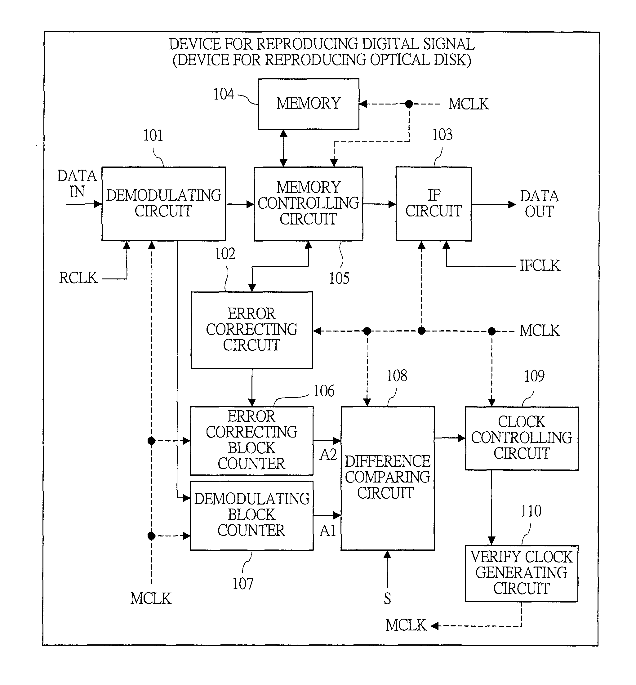
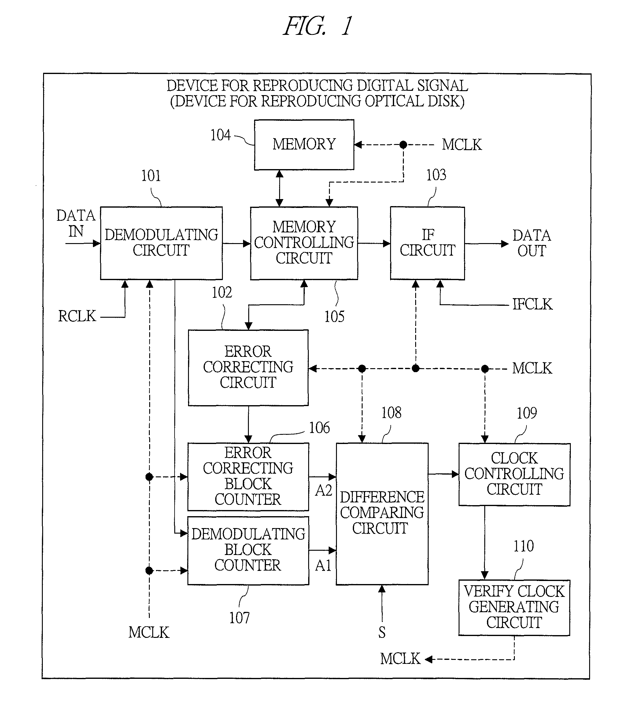
[0037]A device for reproducing digital signals (device for reproducing an optical disk) according to a first embodiment of the present invention will be described with reference to FIG. 1 and FIG. 2. In the first embodiment, such a device for reproducing an optical disk is exemplified that a recorded signal is read to reproduce from a disk such as, for example, DVD and Blu-ray Disc (Trademark).

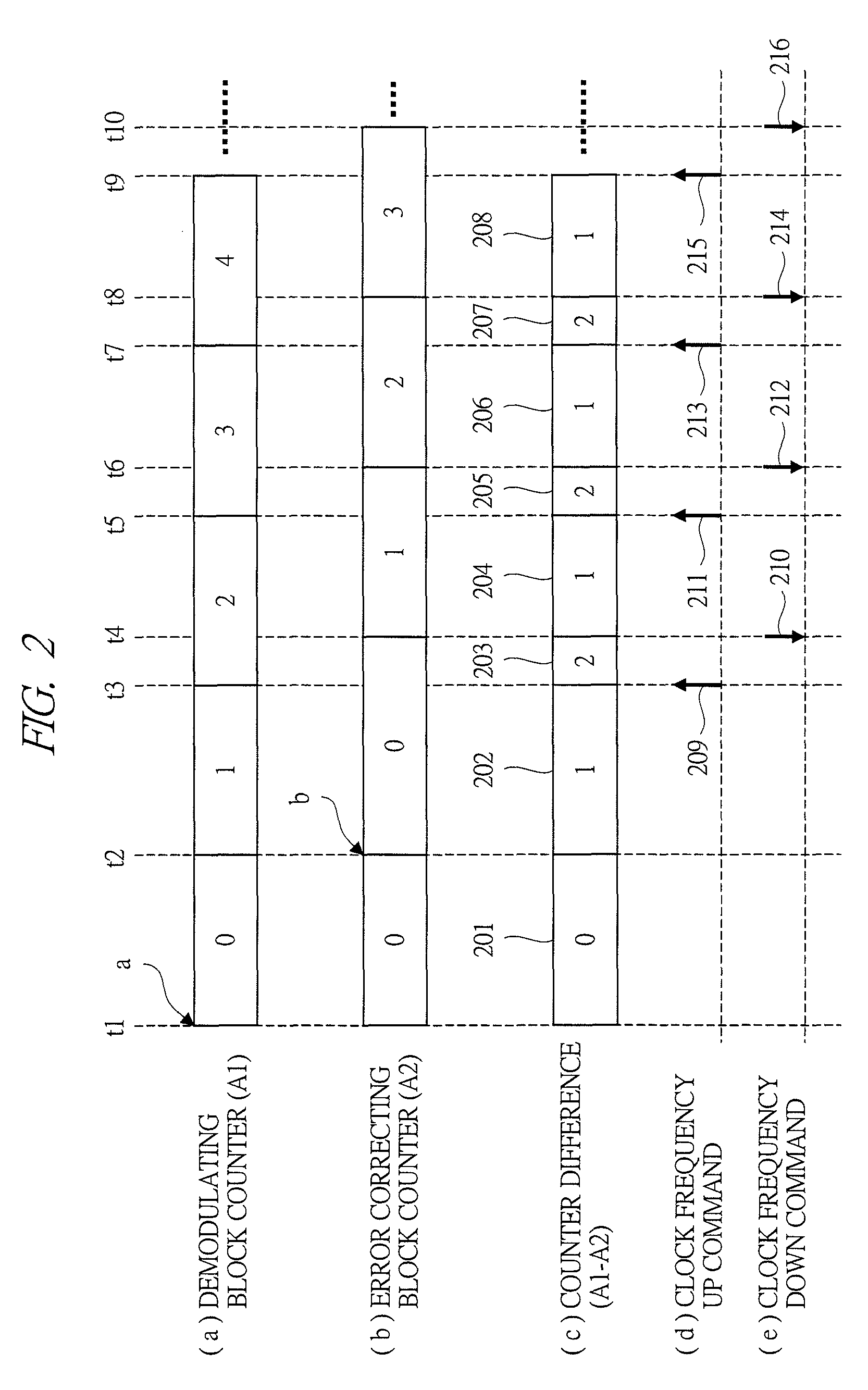
[0038]The first embodiment is characterized by switching up and down of the frequency of the master clock depending on a result of comparing a set value with a difference between a counter value in a demodulating process block and a counter value in an error correcting process block.

[0039]

[0040]FIG. 1 shows a block configuration of a process unit for reproducing digital signals in a device for reproducing an optical disk in a first embodiment. The device includes: a demodulating circuit 101; an error correcting circuit (correcting circuit) 102; an interface (IF) circuit 103 (output circuit); a...

second embodiment

[0072]Next, a device for reproducing digital signals (device for reproducing an optical disk) according to a second embodiment of the present invention will be described with reference to FIG. 3 to FIG. 5. A different point of the second embodiment from the first embodiment is to select and control two types of master clocks.

[0073]

[0074]FIG. 3 shows a block configuration of a unit for a digital signal reproducing process in a device for reproducing an optical disk in a second embodiment. Components having the same symbol are substantially the same in the operation and the like with those of the first embodiment. A different point of FIG. 3 from FIG. 1 is to provide a clock generating circuit 301 and a clock selecting circuit 302 instead of the variable clock generating circuit 110. The clock generating circuit 301 generates two types of a clock with a high frequency (first clock: CLK1) and a clock with a low frequency (second clock: CLK2). The clock selecting circuit 302 selects eit...

third embodiment

[0088]Next, a device for reproducing digital signals (device for reproducing an optical disk) according to a third embodiment of the present invention will be described with reference to FIG. 6 to FIG. 8. The third embodiment is for further efficiently realizing the power saving by characterizing controls of the memory controlling circuit 105 and the error correcting circuit 102 (controls performed by the circuits) in FIG. 1 or FIG. 3 described above. FIG. 6 shows a flow chart of the control of the memory controlling circuit 105, FIGS. 7A and 7B show timing charts of an operation of the error correcting circuit 102, and FIGS. 8A and 8B show timing charts of an operation of the device of the third embodiment.

[0089]

[0090]In FIG. 6, the operation of the memory controlling circuit 105 of the device according to the third embodiment will be described (“S” indicates a process step). Once the operation is started, the memory controlling circuit 105 determines either ending or continuing of...


PUM

PropertyMeasurementUnit
frequencyaaaaaaaaaa
frequencyaaaaaaaaaa
frequencyaaaaaaaaaa

Abstract

A technique capable of realizing a power saving in a device for reproducing/recording digital signals by properly controlling a frequency of a clock. The device for reproducing/recording digital signals (device for reproducing an optical disk) includes: a difference comparing circuit for comparing a first parameter (demodulating block counter) updated each time a process for one correcting block is done in a demodulating circuit with a second parameter (error correcting block counter) updated each time a process of one correcting block is done in an error correcting circuit; and a circuit (clock controlling circuit etc.) for switching a frequency of a master clock (MCLK) depending on a comparison result of the difference comparing circuit. Thereby, the frequency of the clock can be switched both of when the demodulation for one correcting block is ended and when the correcting process for one correcting block is ended by using the switched master clock.

Description

CROSS-REFERENCE TO RELATED APPLICATION[0001]The present application claims priority from Japanese Patent Application No. JP 2008-128198 filed on May 15, 2008, the content of which is hereby incorporated by reference into this application.TECHNICAL FIELD[0002]The present invention relates to a device and a method for recording and reproducing digital signals such as a disk medium. More particularly, the present invention relates to a power saving for a digital signal process of encode and decode.BACKGROUND[0003]It is advantageous in access performance to perform the recording and reproducing of an optical disk such as a DVD and a CD by CAV (Constant Angular Velocity), and therefore, the recording and reproducing by CAV is generally used. However, in this case, a transfer rate of a data reproduced from a disk and a recording rate of a data recorded to the disk change in a range of about 2.5 times. According to this, Jyh-Shin Pan et al., “Fully Integrated CMOS SoC for 56 / 18 / 16 CD / DVD-d...

Claims


Application Information

Patent Timeline
Patent Type & Authority Patents(United States)
IPC IPC(8): G11B5/09
CPCG11B19/02G11B20/10222G11B20/14G11B20/18G11B2020/10981G11B2020/1222G11B2020/1244
Inventor NAGAI, YUTAKA
Owner RENESAS ELECTRONICS CORP
Why Eureka
Try Eureka