Lighting apparatus and luminaire

a technology of light-emitting devices and light-emitting devices, which is applied in the direction of electroluminescent light sources, electric lighting sources, and use of semiconductor lamps. it can solve the problems of reducing the light emission of reducing the current supplied to the solid-state light-emitting device. it achieves the effect of suppressing flicker

Inactive Publication Date: 2016-03-03
PANASONIC INTELLECTUAL PROPERTY MANAGEMENT CO LTD
View PDF11 Cites 7 Cited by
  • Summary
  • Abstract
  • Description
  • Claims
  • Application Information

AI Technical Summary

Benefits of technology

[0015]With the lighting apparatus and the luminaire according to the present disclosure, it is possible to suppress flickering even when momentary pow...

Problems solved by technology

However, the conventional lighting apparatus as described above which includes the DC/DC converter that performs control under which an upper limit is set on the ON time of the switching element poses a problem as described below.
When momentary power failure (instantaneous power failure) or momentary voltage drop (instantaneous voltage drop) occurs in a commercial power supply that supplies power to the AC/DC converter, there is a problem that a current supplied to a solid-state light-emitti...

Method used


Image

  • Lighting apparatus and luminaire
  • Lighting apparatus and luminaire
  • Lighting apparatus and luminaire

Examples


embodiment 1

[0032]First, a lighting apparatus according to Embodiment 1 of the present disclosure will be described.

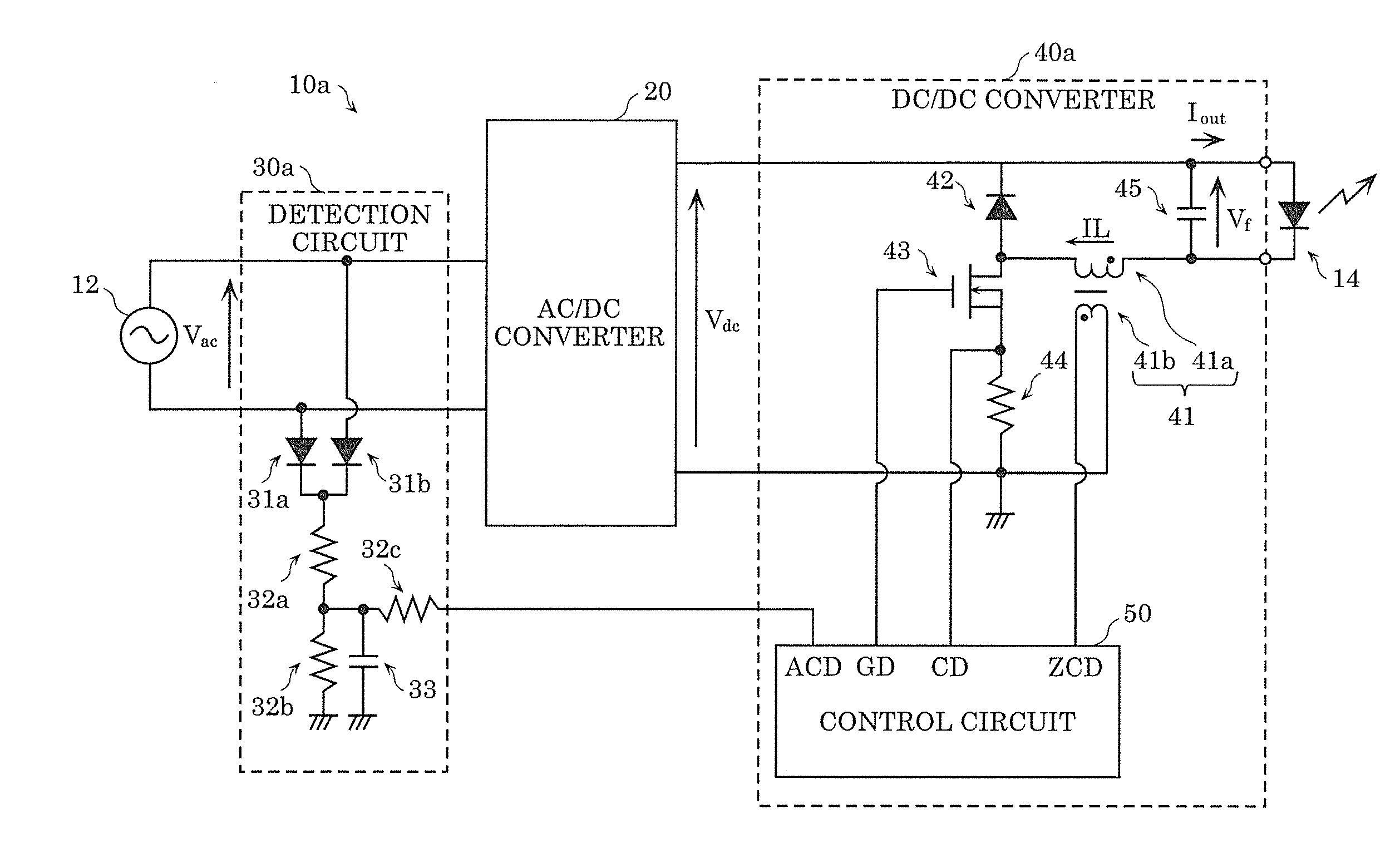
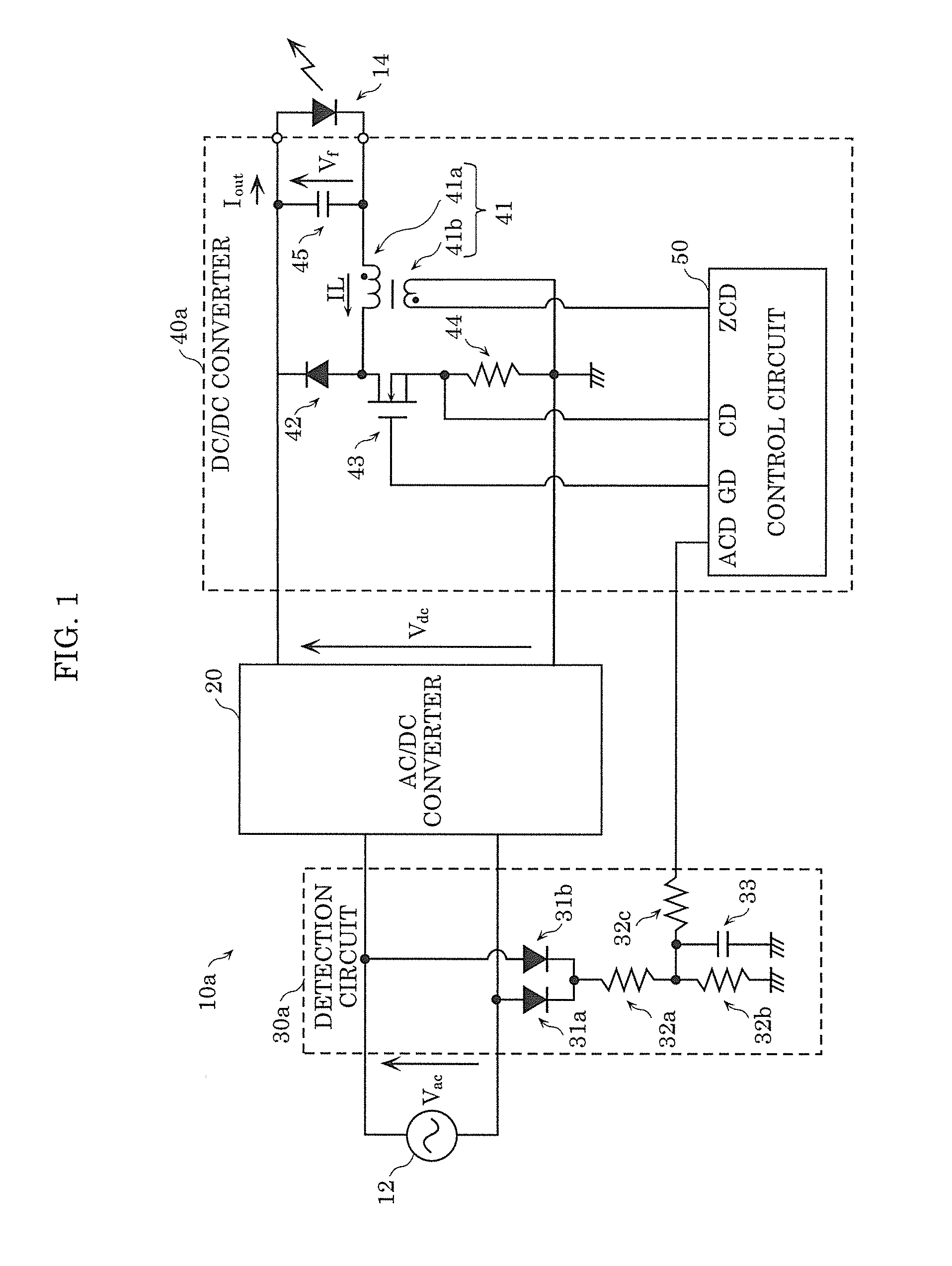
[0033]FIG. 1 is a circuit diagram of lighting apparatus 10a according to Embodiment 1 of the present disclosure. FIG. 1 also illustrates AC power supply 12 (a commercial power supply, for example) which generates an AC voltage provided to lighting apparatus 10a, and LED 14 which is an example of a solid-state light-emitting device to which a current output from lighting apparatus 10a is supplied.

[0034]As illustrated in FIG. 1, lighting apparatus 10a is an apparatus which supplies a current (output current Iout) to LED 14, and includes AC / DC converter 20, detection circuit 30a, and DC / DC converter 40a.

[0035]AC / DC converter 20 is a circuit which converts an AC voltage to a first DC voltage. AC / DC converter 20 converts AC voltage Vac, which is provided from AC power supply 12, to DC voltage Vdc, according to the present embodiment. AC / DC converter 20 includes a diode bridge which re...

embodiment 2

[0074]Next, a lighting apparatus according to Embodiment 2 of the present disclosure will be described.

[0075]FIG. 8 is a circuit diagram of lighting apparatus 10b according to Embodiment 2 of the present disclosure. Lighting apparatus 10b is an apparatus which supplies a current to LED 14, and includes AC / DC converter 20, detection circuit 30b, and DC / DC converter 40a. Compared to lighting apparatus 10a according to Embodiment 1, lighting apparatus 10b includes detection circuit 30b of a different type. In the following description, the same elements as those in Embodiment 1 are assigned with the same reference signs, and description is omitted (the same holds true for the subsequent embodiments).

[0076]Detection circuit 30b is an example of a circuit which detects an AC voltage provided to AC / DC converter 20 or a first DC voltage output from AC / DC converter 20, and detects DC voltage Vdc output from AC / DC converter 20, according to the present embodiment. Detection circuit 30b inclu...

embodiment 3

[0080]Next, a lighting apparatus according to Embodiment 3 of the present disclosure will be described.

[0081]FIG. 10 is a circuit diagram of lighting apparatus 10c according to Embodiment 3 of the present disclosure. Lighting apparatus 10c is an apparatus which supplies a current to LED 14, and includes AC / DC converter 20, detection circuit 30c, and DC / DC converter 40a. Compared to lighting apparatus 10a according to Embodiment 1, lighting apparatus 10c includes detection circuit 30c of a different type.

[0082]Detection circuit 30c is an example of a circuit which detects an AC voltage provided to AC / DC converter 20 or a first DC voltage output from AC / DC converter 20, and detects AC voltage Vac provided to AC / DC converter 20 according to the present embodiment. As illustrated in FIG. 10, detection circuit 30c includes rectifiers (diodes 31a and 31b) which converts an AC voltage to a DC voltage, voltage dividers (resistors 32a and 32b), and MCU (microcomputer) 37.

[0083]According to d...


PUM


Abstract

Lighting apparatus includes: AC/DC converter which converts AC voltage Vac to DC voltage Vdc; DC/DC converter which converts DC voltage Vdc to a DC voltage to be applied to LED; and detection circuit which detects AC voltage Vac. DC/DC converter includes switching element, and control circuit that performs a control of repeatedly turning on and off switching element in a boundary conduction mode. Control circuit performs the control under which ON time Ton is kept from exceeding an upper limit that is previously determined, and raises the upper limit when AC voltage Vac detected by detection circuit falls below a predetermined value. ON time Ton is a period of time during which switching element is kept ON.

Description

CROSS REFERENCE TO RELATED APPLICATION[0001]This application claims the benefit of priority of Japanese Patent Application Number 2014-173044, filed Aug. 27, 2014, the entire content of which is hereby incorporated by reference.BACKGROUND OF THE INVENTION[0002]1. Field of the Invention[0003]The present disclosure relates to a lighting apparatus which supplies a current to a solid-state light-emitting device, and a luminaire including the lighting apparatus.[0004]2. Description of the Related Art[0005]As a lighting apparatus which supplies a current to a solid-state light-emitting device such as an LED (light-emitting diode), an apparatus which includes an AC / DC converter and a DC / DC converter connected to the AC / DC converter has been proposed (see, for example, Patent Literature 1: Japanese Unexamined Patent Application Publication No. 2013-30416).[0006]In the lighting apparatus according to Patent Literature 1, the DC / DC converter includes a chopper circuit having a switching eleme...

Claims


Application Information

Patent Timeline
IPC IPC(8): H05B44/00
CPCH05B33/0815H05B33/0887H05B45/37Y02B20/30H05B45/3725H02M3/33546
Inventor SEKI, KEISUKEKAMOI, TAKESHIYAMAHARA, DAISUKE
Owner PANASONIC INTELLECTUAL PROPERTY MANAGEMENT CO LTD
Why Eureka
Try Eureka