
Electrical connection box

a technology of electrical connection box and electrical connection box, which is applied in the direction of electrical/fluid circuit, electrical apparatus casing/cabinet/drawer, electrical components, etc., can solve the problems of short circuit of electronic components and water entering the electrical connection box, and achieve space-saving electrical connection box

Active Publication Date: 2016-03-10
FURUKAWA ELECTRIC CO LTD +1
View PDF11 Cites 2 Cited by
  • Summary
  • Abstract
  • Description
  • Claims
  • Application Information

AI Technical Summary

Benefits of technology

The patent text describes a problem where there is a drain channel on a board, which prevents electronic components from being placed there, which hinders the downsizing of the electrical connection box.

Problems solved by technology

Here, water may enter the electrical connection box when the covering is damaged or during a maintenance operation.
Entry of water into the electrical connection box and exposure of an electronic component to the water may cause short-circuit of the electronic component.

Method used


Image

  • Electrical connection box
  • Electrical connection box
  • Electrical connection box

Examples


Embodiment Construction

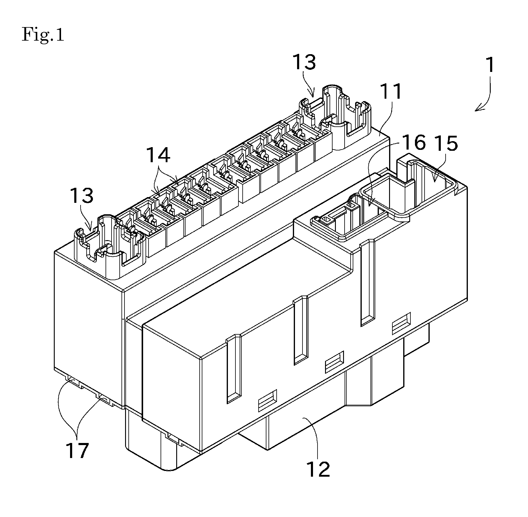
[0029]Next, an embodiment of the present invention will be described with reference to the drawings. FIG. 1 is a perspective view showing an external appearance of an electrical connection box 1 according to an embodiment of the present invention.

[0030]The electrical connection box 1 is configured as a junction box for use in an automobile. As shown in FIG. 1, the electrical connection box 1 is externally covered with an upper covering 11 and a lower covering 12.

[0031]The upper covering 11 has connector holes 13 to 16. Connectors are received in the connector holes 13 to 16. Through the connectors, the electrical connection box 1 is connected to electrical devices of the automobile. The lower covering 12 also has connector holes, though not shown.

[0032]Drain ports 17 are provided between the upper covering 11 and the lower covering 12. The drain ports 17 discharge, to the outside, water having entered the electrical connection box 1 through a damaged portion of the upper covering 11...


PUM


Abstract

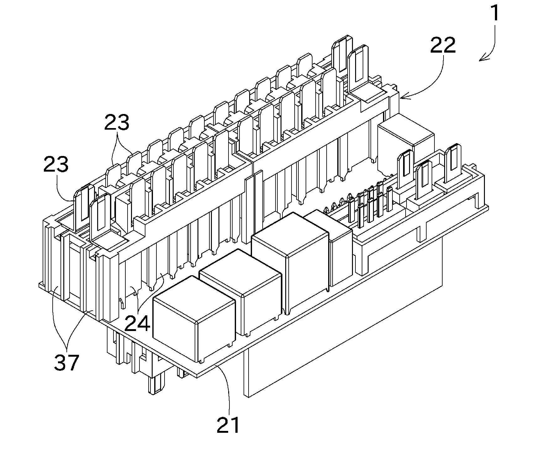
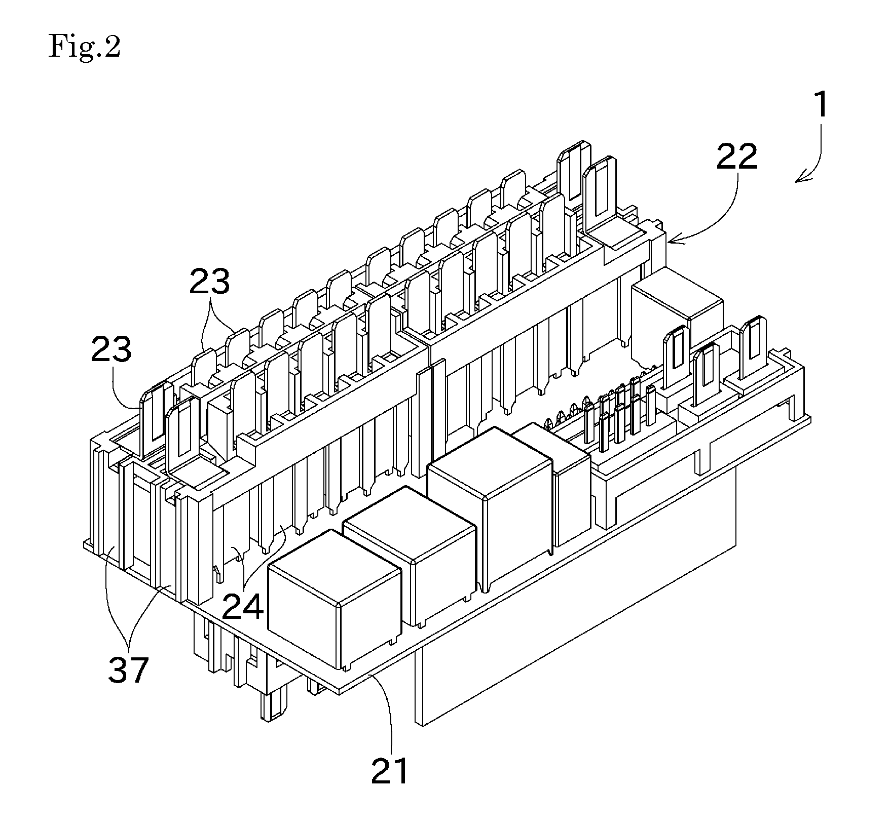
Provided is an electrical connection box that achieves downsizing by means of efficient arrangement of electronic components and terminals on a board. An electrical connection box (1) includes a board (21), a terminal holder (22), flat-plate terminals (23), and electronic components (24). The terminal holder (22) is mounted to the board (21). The flat-plate terminal (23) includes a first portion (41), a second portion (42), and a third portion (43). The first portion (41) is connected to the board (21), and extends substantially perpendicularly from the board (21). The second portion (42) is connected to the first portion (41), and extends substantially in parallel with the board (21). The third portion (43) is connected to the second portion (42), is connectable to a connector, and extends substantially perpendicularly to the board (21). The electronic component (24) is arranged between the second portion (42) of the flat-plate terminal (23) and the board (21).

Description

TECHNICAL FIELD[0001]The present invention relates to an electrical connection box that houses therein electronic components, terminals, and the like. In more detail, the present invention relates to a configuration in which the electronic components and the terminals are arranged such that the electrical connection box can be downsized.BACKGROUND ART[0002]Conventionally known is an electrical connection box in which electronic components such as a fuse and a relay mounted on a board are covered with a covering. The electrical connection box is installed in, for example, an engine room of an automobile. The electrical connection box includes a large number of terminals, and the terminals are connected to an electrical device, and the like, arranged in the engine room.[0003]Here, water may enter the electrical connection box when the covering is damaged or during a maintenance operation. Entry of water into the electrical connection box and exposure of an electronic component to the ...

Claims


Application Information

Patent Timeline
IPC IPC(8): H05K7/02
CPCH05K7/026B60R16/0238
Inventor KAMINISHI, TOSHIMICHIJINGAMA, SHINICHINAIMI, FUMIKAZU
Owner FURUKAWA ELECTRIC CO LTD
Learn More