Foot morphometric measuring device

a technology of morphometric measuring and foot, which is applied in the field of foot measuring device and method, can solve problems such as undeveloped systems

Inactive Publication Date: 2016-03-17
UTI LLP
View PDF8 Cites 8 Cited by
  • Summary
  • Abstract
  • Description
  • Claims
  • Application Information

AI Technical Summary

Benefits of technology

[0020]In another embodiment, the foot measuring device further comprises at least one support member attached to the base top surface; and a rail extending longitudinally along the base, the rail held above the base by the at least one support member; wherein the arch height measurement member is slidingly and pivotably engaged

Problems solved by technology

A review of the prior art reveals that

Method used


Image

  • Foot morphometric measuring device
  • Foot morphometric measuring device
  • Foot morphometric measuring device

Examples


Embodiment Construction

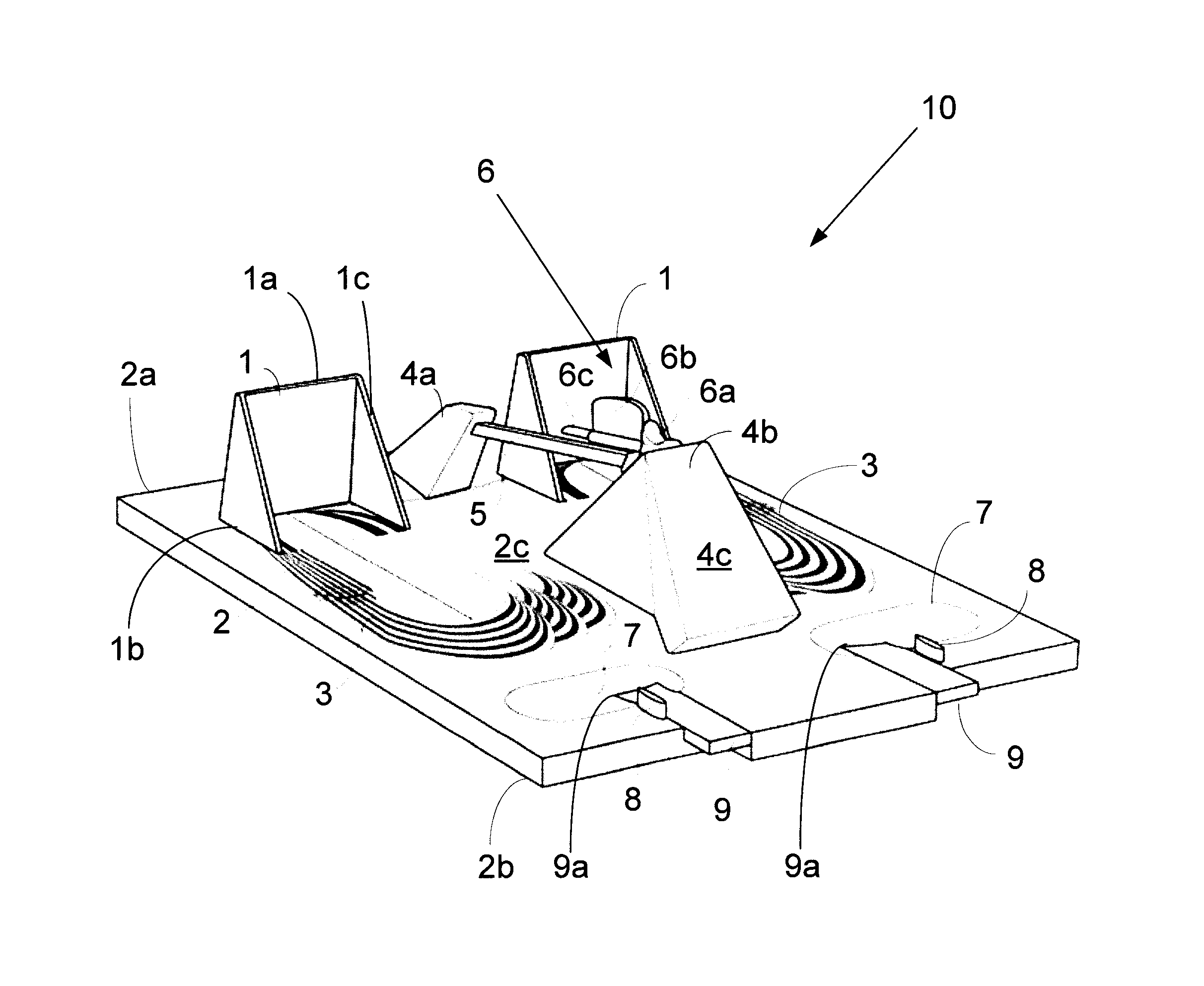
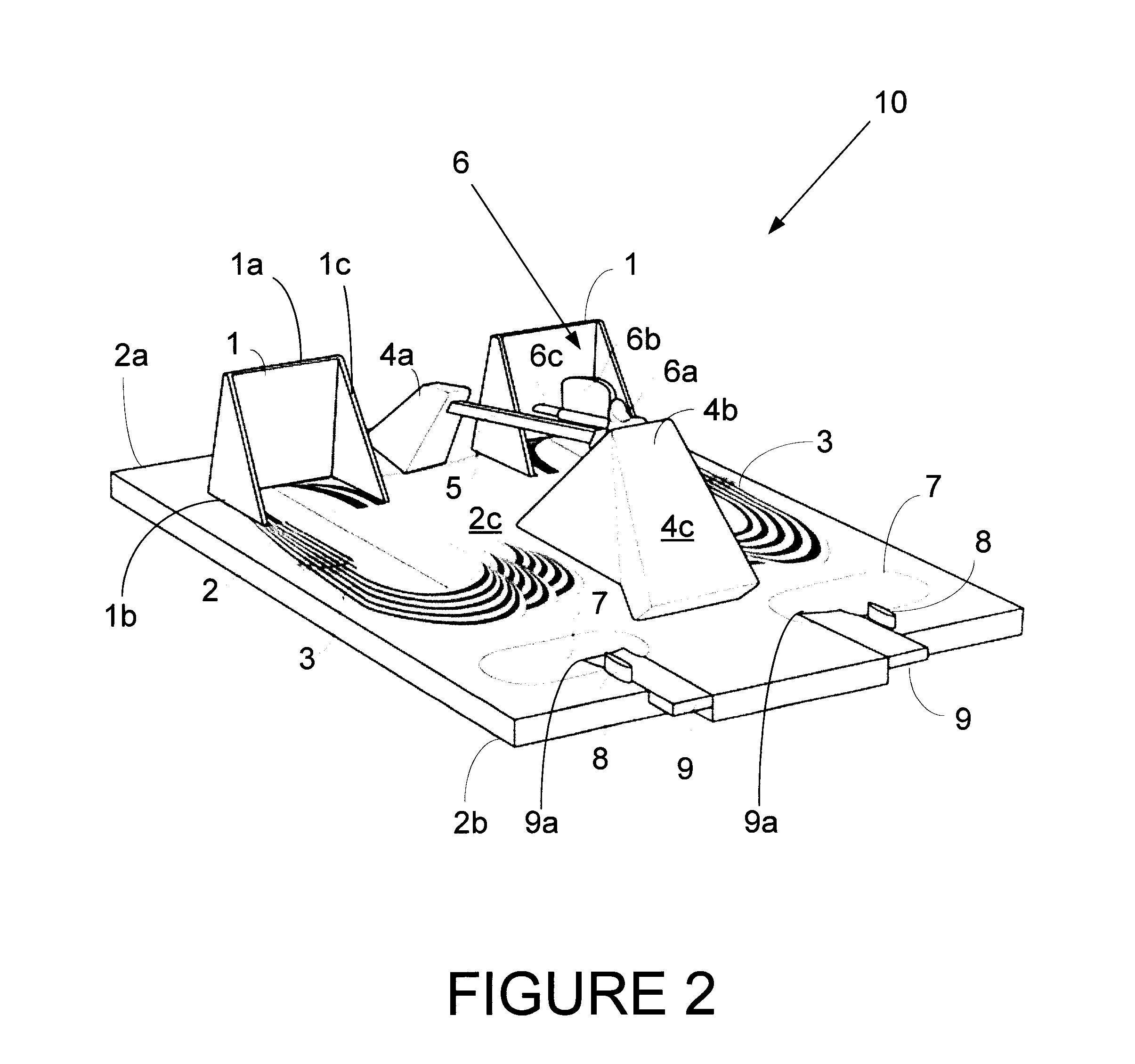
[0052]With reference to the figures, a foot measurement device and method are described. FIG. 2 illustrates an overview of all components included in a preferred embodiment of the foot measurement device 10. The device comprises a base 2 having a rear end 2a and a front end 2b with a flat non-slip top surface 2c wide enough to accommodate two feet and robust enough to support a standing person. A left and right foot size and alignment graphic 3 is printed or otherwise affixed to the base surface 2c. A left and right heel abutment member 1, a first and second support member 4a, 4b and a left and right toe separation member 8 are mounted to the top surface of the base 2 in the arrangement illustrated in FIG. 2. A left and right depression 7 for the placement of the ball of the foot are located towards the front end 2b of the base as illustrated in FIGS. 2 and 4. An inclined rail 5 is mounted between the first and second support member 4a, 4b to guide the movement of an arch height mea...


PUM


Abstract

A foot measuring device and method measure foot last/curvature, foot width, foot length, arch height, foot volume, first metatarsophalangeal (MTP) joint flexibility and standing rear foot pronation. The foot measuring device includes a base having a heel abutment member, a foot size and alignment graphic, an arch height measurement system, and a MTP joint flexibility measurement lever.

Description

FIELD OF THE INVENTION[0001]The invention relates to a foot measuring device and method for the purpose of fitting shoes based on the volume and shape of a foot. Specifically the device and method measure foot volume based on arch height, first metatarsal-phalangeal joint flexibility, standing rear foot pronation, and foot length, width and curvature.BACKGROUND OF THE INVENTION[0002]In 1925, Charles F. Brannock invented a foot-measuring device that is known throughout the world as The Brannock™. As is well known, The Brannock™ device is the most common device for computing a person's shoe size. That is, almost every shoe store in the world uses The Brannock™ and very few competing devices have since been developed. However, The Brannock™ is based on sizes that are not used by the industry leaders in shoe manufacturing such as Nike™, Adidas™, and New Balance™. Thus, having one's foot measured, for either length or width, using this device is generally not accurate for reasons as expl...

Claims


Application Information

Patent Timeline
IPC IPC(8): A61B5/107A61B5/00
CPCA61B5/1074A61B5/1072A61B5/6829A43D1/027A43D1/02
Inventor FERBER, REEDOSIS, SEAN
Owner UTI LLP
Why Eureka
Try Eureka