
Method for constructing cylindrical tank

a technology of cylindrical tanks and lateral plates, which is applied in the direction of vessel construction details, container discharge methods, building repairs, etc., can solve the problems of few or no structures usable to prevent the lateral plate falling of the inner tank

Inactive Publication Date: 2016-03-24
IHI CORP
View PDF36 Cites 8 Cited by
  • Summary
  • Abstract
  • Description
  • Claims
  • Application Information

AI Technical Summary

Benefits of technology

The present disclosure provides a method for constructing a cylindrical tank using the jack-up construction system, which prevents the inner tank lateral plate from falling without complicated operations. The method includes the steps of assembling the metal inner tank, raising the inner tank lateral plate, and welding the next-stage inner tank lateral plate onto the lower section of the raised inner tank lateral plate. A guide pair is installed to sandwich the raised inner tank lateral plate and prevent it from falling. The guide pair includes guide rollers or a first and second guide member that roll on the plate surfaces of the raised inner tank lateral plate. This reduces friction and noise during the transfer of the next-stage inner tank lateral plate. The method also includes installing the guide members at a level below or above the key nut to avoid interference and ensure a smooth transfer of the inner tank lateral plate.

Problems solved by technology

However, around the next-stage inner tank lateral plate that is to be attached to the lower section of the raised inner tank lateral plate, there are few or no structures usable for preventing the inner tank lateral plate from falling.

Method used


Image

  • Method for constructing cylindrical tank
  • Method for constructing cylindrical tank
  • Method for constructing cylindrical tank

Examples


Embodiment Construction

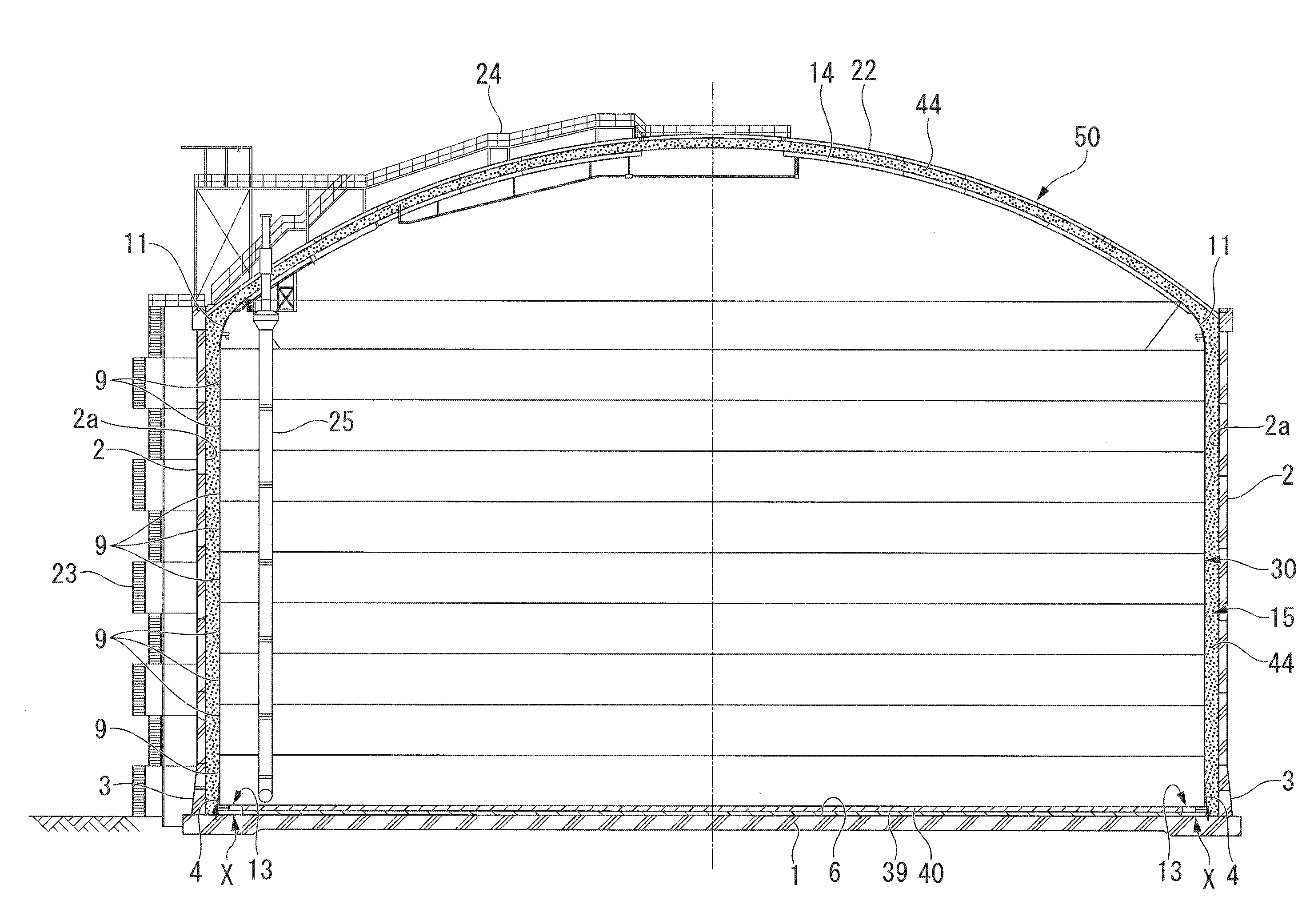
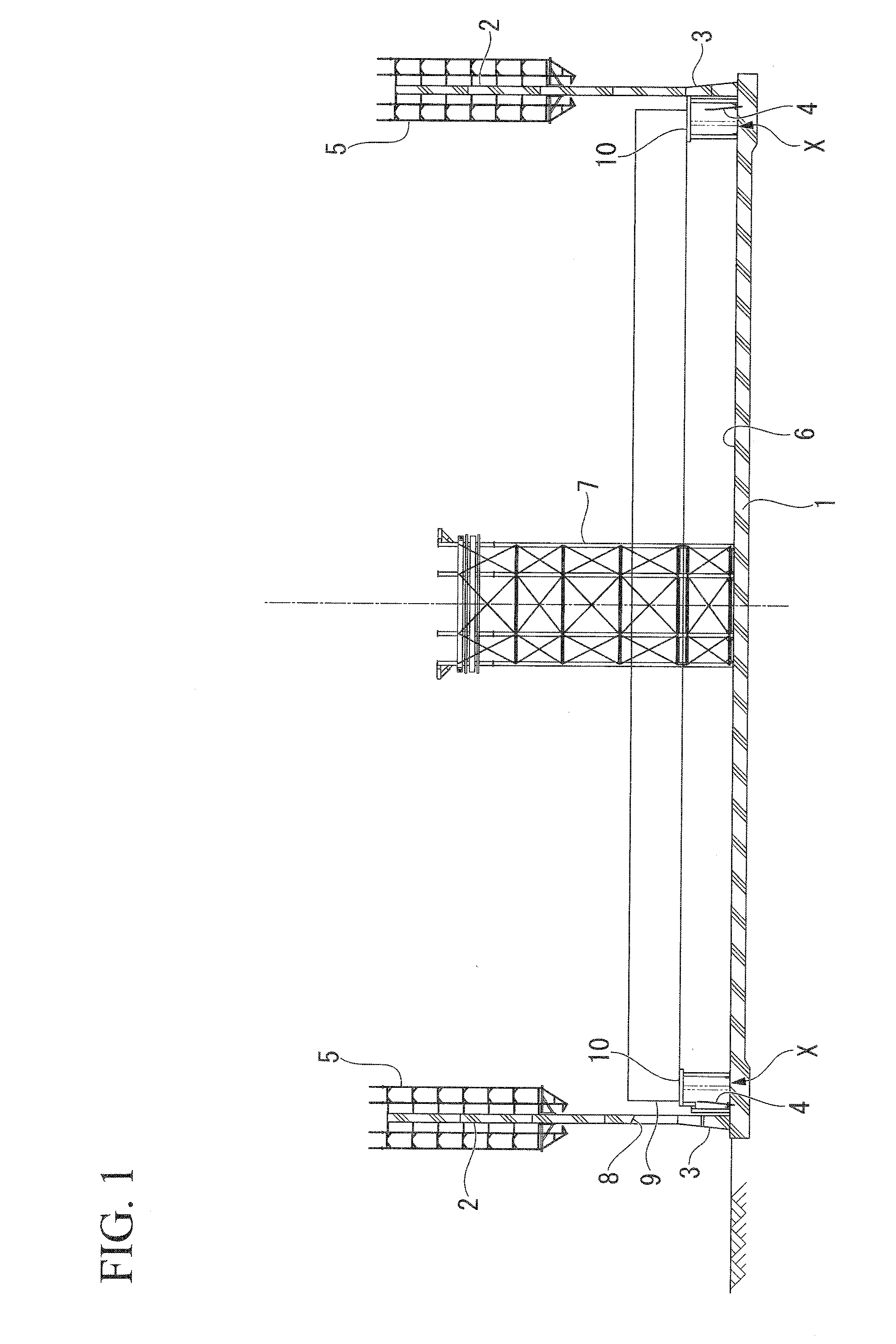
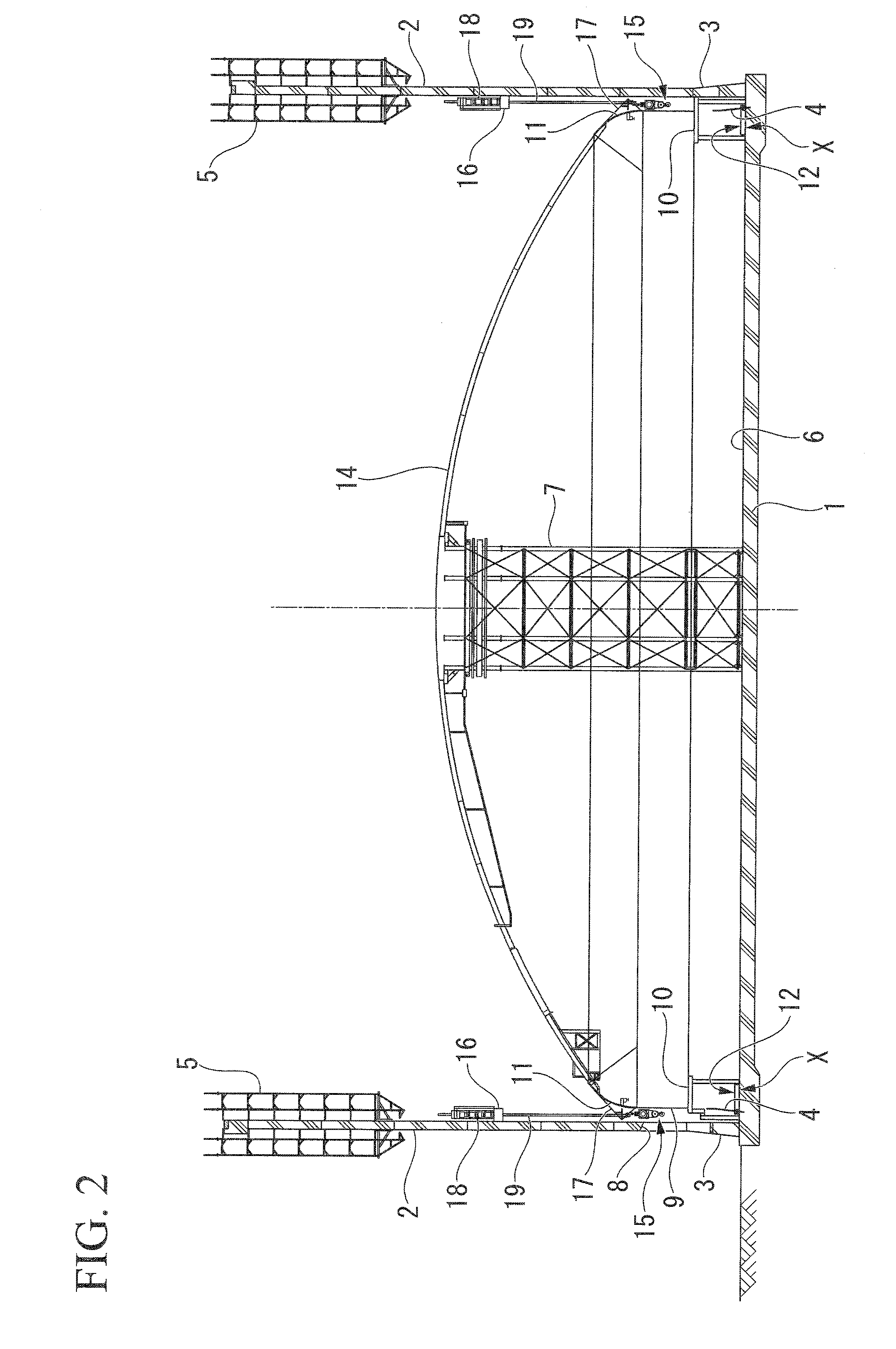
[0030]Hereunder is a description of a method for constructing a cylindrical tank according to the present disclosure, with reference to the drawings. In the following description, a ground-type PC (prestressed concrete) double-shell tank configured to store LNG will be used as a cylindrical tank, by way of example.

[0031]As shown in FIG. 1, a substantially disc-like base plate 1 is firstly constructed in the present method. On an outer circumferential edge of the base plate 1, there is erected a base part 3 on which a PC wall 2 (outer tank) is to be assembled. Along an internal side of the base part 3, inner tank anchor straps 4 are installed. Then, the PC wall 2 is formed on the base part 3 by casting. For the formation of the PC wall 2 by casting, a foot scaffold 5 is provided on both of the internal side and the external side, and mold (not shown in the figure) is installed.

[0032]Subsequently, a base portion liner 6 is laid on the base plate 1. At the central portion of the base p...


PUM


Abstract

There is provided a method for constructing a cylindrical tank, including the step of assembling a metal inner tank by individually and sequentially conducting, on an internal side of a PC wall, raising of an inner tank lateral plate by a jack-up unit and welding of a next-stage inner tank lateral plate onto a lower section of the raised inner tank lateral plate, further including the step of installing a guide pair configured to sandwich the raised inner tank lateral plate onto the next-stage inner tank lateral plate that is to be welded therebeneath. As a result, in the case of adopting the jack-up construction system, it is possible to prevent an inner tank lateral plate from being attached next from falling.

Description

[0001]This application is a continuation application based on a PCT Patent Application No. PCT / JP2014 / 066998, filed on Jun. 26, 2014, whose priority is claimed on Japanese Patent Application 2013-135162, filed on Jun. 27, 2013. The contents of both the PCT Application and the Japanese Application are incorporated herein by reference.TECHNICAL FIELD[0002]The present disclosure relates to a method for constructing a cylindrical tank.RELATED ART[0003]Cylindrical tanks with a dual-shell structure that have an inner tank and an outer tank are used for storing cryogenic liquid such as LNG (liquefied natural gas) and LPG (liquefied petroleum gas). Patent Document 1 discloses a cylindrical tank that has an inner tank made of metal and an outer tank made of concrete.[0004]Patent Document 1 discloses a method of constructing a metal inner tank and a concrete outer tank at the same time in order to make the construction period of the cylindrical tank shorter. To be more specific, jack stands a...

Claims


Application Information

Patent Timeline
IPC IPC(8): E04H7/06E04B1/35E04H7/18F17C1/02
CPCE04B1/3522F17C1/02E04H7/06E04H7/18F17C2203/0602F17C2203/011F17C2209/221F17C2221/033F17C2221/035F17C2201/0104E04H5/10E04H7/065F17C13/004F17C2201/0109F17C2201/0119F17C2201/032F17C2201/052F17C2203/0341F17C2203/0629F17C2203/0639F17C2203/0678F17C2203/0695F17C2209/232F17C2209/234F17C2209/236F17C2209/238F17C2223/0153F17C2223/0161F17C2270/0134
Inventor YAMADA, JUICHIROKATO, SHIGEKI
Owner IHI CORP
Learn More