
Image forming apparatus

Active Publication Date: 2016-03-24
CANON KK
View PDF2 Cites 3 Cited by
  • Summary
  • Abstract
  • Description
  • Claims
  • Application Information

AI Technical Summary

Benefits of technology

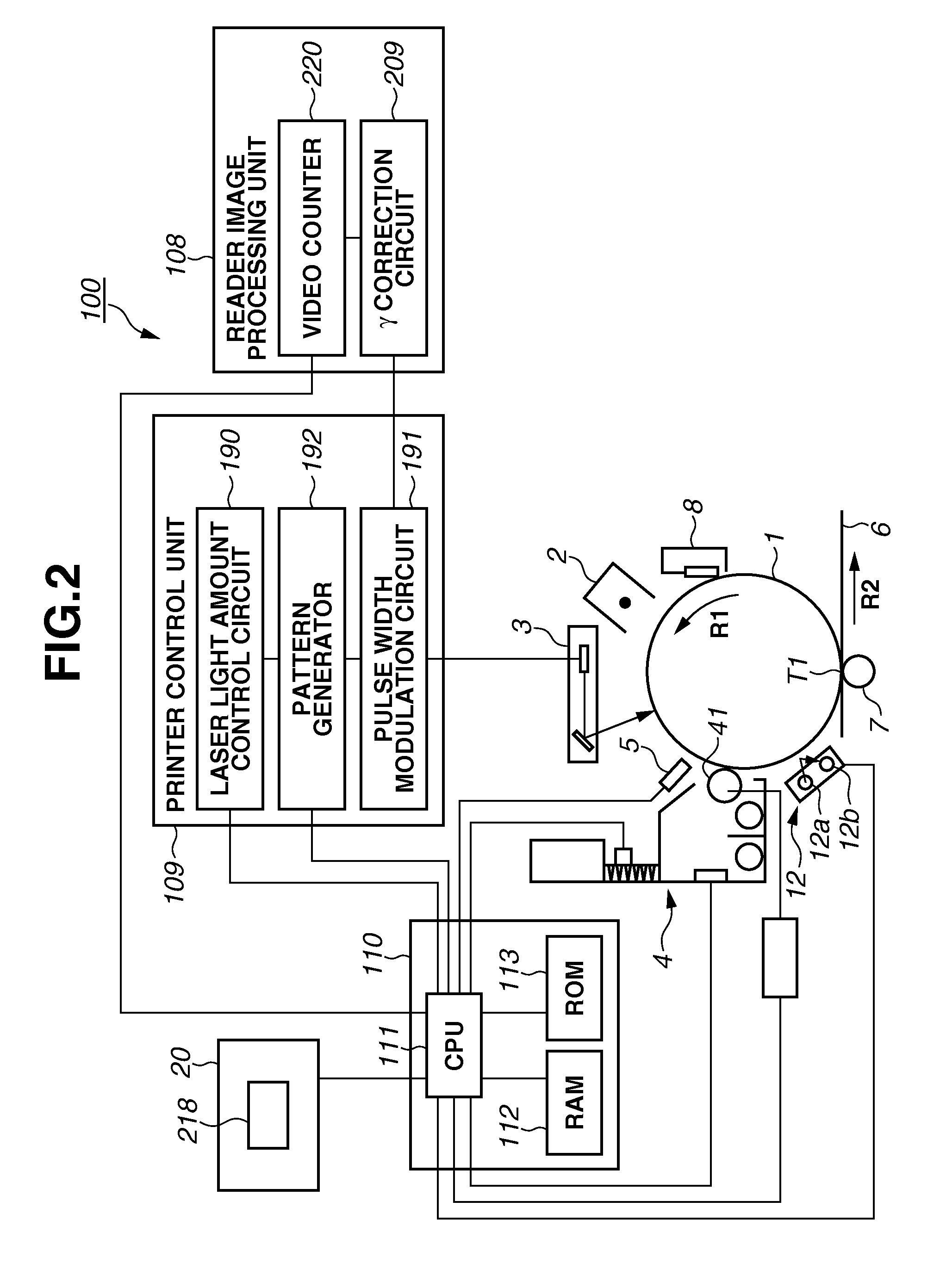
The present invention is about an image forming apparatus that can convert image data and form an image using toner in a container. The apparatus includes an image bearing member, a conversion unit, an image forming unit, a controller, a measurement unit, and a generation unit. The generation unit generates a conversion condition based on measurement data from the measurement unit, and causes the image forming unit to form a measuring image on the image bearing member. The conversion condition and a feedback condition are used to convert the image data and form the image. The second measuring image is formed during a period from when the controller has performed toner discharge processing until the image forming unit forms the image, and the second feedback condition has a larger correction amount than the first feedback condition. The technical effects of this invention include improved accuracy and efficiency in image formation.

Problems solved by technology

However, when, for example, the image forming apparatus forms a plurality of images at low toner consumption, the consumed developer is slight and the developer contained in the development device thus can be excessively charged.
Even when the charge amount of the developer in the development device excessively increases, the image forming apparatus can decrease the amount of the developer in the development device by forming a pattern image and discharging the developer, and further can decrease the charge amount of the developer in the development device due to new toner supplied to the development device.

Method used


Image

  • Image forming apparatus
  • Image forming apparatus
  • Image forming apparatus

Examples


Embodiment Construction

[0023]A first exemplary embodiment according to the present invention will be first described.

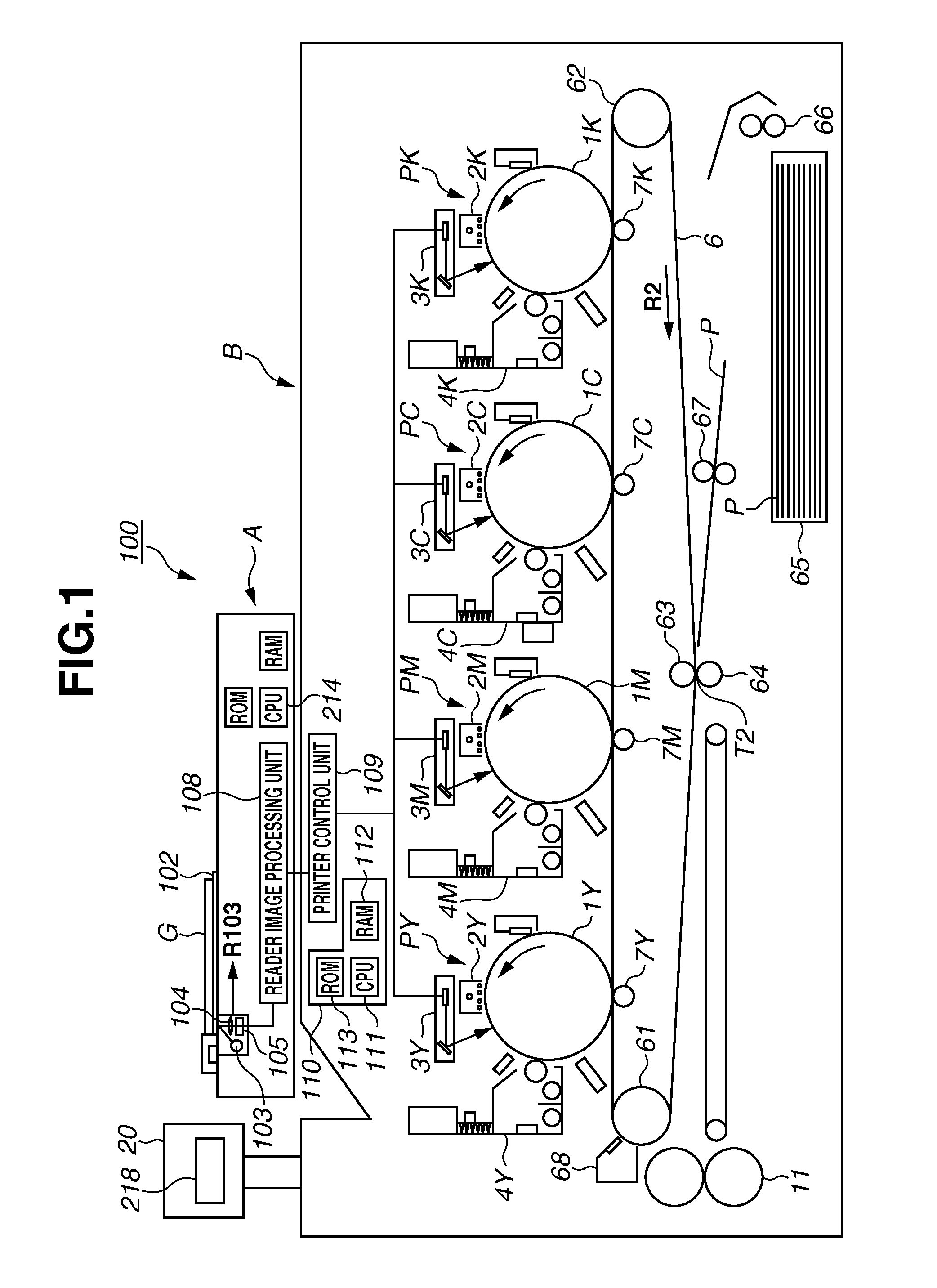
[0024]As illustrated in FIG. 1, an image forming apparatus 100 is a full-color printer in which yellow, magenta, cyan, and black image forming units PY, PM, PC, and PK are arranged along an intermediate transfer belt 6.

[0025]A yellow-component toner image is formed on a photosensitive drum 1Y at the image forming unit PY and is transferred onto the intermediate transfer belt 6. A magenta-component toner image is formed on a photosensitive drum 1M at the image forming unit PM and is transferred onto the intermediate transfer belt 6 in such a way as to overlap the yellow-component toner image. A cyan-component toner image and a black-component toner image are formed on a photosensitive drum 1C at the image forming unit PC and a photosensitive drum 1K at the image forming unit PK, respectively, and are sequentially transferred onto the intermediate transfer belt 6 in such a way as to overlap t...


PUM


Abstract

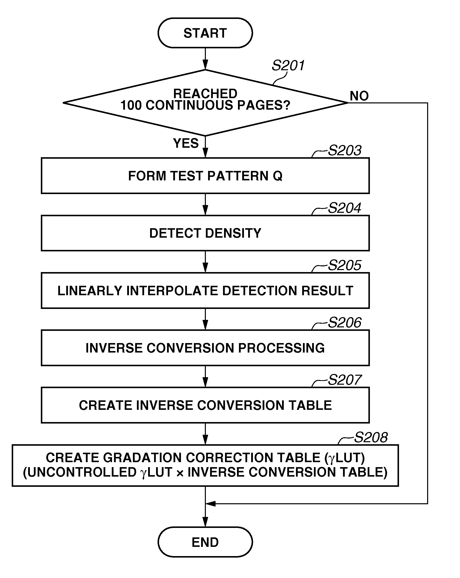
An image forming apparatus includes a conversion unit that converts image data based on a conversion condition, an image forming unit that forms an image based on the converted image data, a measurement unit that measures a measuring image, and a generation unit that controls the image forming unit to form a first measuring image while the image forming unit is continuously forming images, and generates the conversion condition based on first measurement data of the first measuring image and a first feedback condition. The generation unit controls the image forming unit to form a second measuring image during a period from when toner discharge processing has been performed until the image forming unit forms a subsequent image, and generates the conversion condition based on second measurement data of the second measuring image, and a second feedback condition with a larger correction amount than the first feedback condition.

Description

BACKGROUND OF THE INVENTION[0001]1. Field of the Invention[0002]The present invention relates to density adjustment control.[0003]2. Description of the Related Art[0004]An electrophotographic image forming apparatus forms an electrostatic latent image on a photosensitive member based on image data, and develops the electrostatic latent image using developer in a development device to thereby form an image. The development device frictionally charges the developer in the development device to thereby change the charge amount of the developer. It is known that a density of an image formed by an image forming apparatus changes depending on the charge amount of developer in a development device. When the charge amount of the developer decreases, the density of the image formed by the image forming apparatus becomes higher. On the other hand, when the charge amount of the developer increases, the density of the image formed by the image forming apparatus becomes lower.[0005]It is importa...

Claims


Application Information

Patent Timeline
IPC IPC(8): G03G15/00
CPCG03G15/556G03G15/5041G03G15/5058G03G2215/00037G03G2215/00755
Inventor SHIRAFUJI, YASUHITO
Owner CANON KK
Learn More