Acceleration detection device

Active Publication Date: 2013-08-01
NISSAN MOTOR CO LTD
View PDF1 Cites 3 Cited by
  • Summary
  • Abstract
  • Description
  • Claims
  • Application Information

AI Technical Summary

Benefits of technology

[0003]However, in the example described above, the acceleration signal detected during the transition from the stationary state to the running state includes a vehicle body vibration component due to an uneven road or movement of the occupant in vehicle. Thus, an exce

Problems solved by technology

However, in the example described above, the acceleration signal detected during the transition from the stationary state to the running state includes a vehicle body vibration component due to a

Method used


Image

  • Acceleration detection device
  • Acceleration detection device
  • Acceleration detection device

Examples


first embodiment

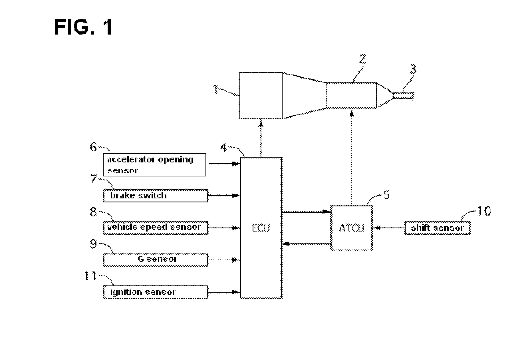
[0018]Referring to FIG. 1, a system diagram is illustrated, to which an acceleration detection device of the first embodiment is applied. The output of engine 1 is, after a prescribed change by automatic transmission 2 connected to engine 1, outputted from output shaft 3 to driving wheels not shown. The vehicle is equipped with engine controller (ECU) 4 and automatic transmission controller (ATCU) 5 for controlling engine 1 and automatic transmission 2 respectively based on output signals of various sensors and the like described below. Both controllers 4, 5 are able to communicate to each other.

[0019]The vehicle is mounted with various sensors such as an accelerator opening sensor 6, brake switch 7, vehicle speed sensor 8, acceleration sensor (G sensor) 10, shift sensor 10, and ignition sensor 11.

[0020]The accelerator opening sensor 6 detects an accelerator opening and outputs the accelerator opening signal to ECU 4. Brake switch 7 outputs a brake switch signal to ECU 4 indicating ...

second embodiment

[0074]Now description is made of the effects. FIG. 8 is a time chart depicting the inhibitory operation of correction amount at the time of the zero point correction in the

[0075]The correction restriction or limiting unit 20 limits or restricts, when the after-restriction correction value Gdlim is positive, the increase amount from the previous value Ddlim n−1 at the zero point correction immediately after ignition switch being ON. More specifically the correction restriction unit 20 limits the increase amounts to Gdlv−1 (acceleration corresponding to 5% gradient) at first time of correction and limits to the limit value Gdlv−2 (acceleration corresponding to 1% gradient) at the second and subsequent times.

[0076]Therefore, as shown in FIG. 8, when a drift error is occurring corresponding to the acceleration of 5% gradient immediately following ignition switch being turned ON, the correction amount at the first time of zero point correction may be made to the same as the drift error. ...

third embodiment

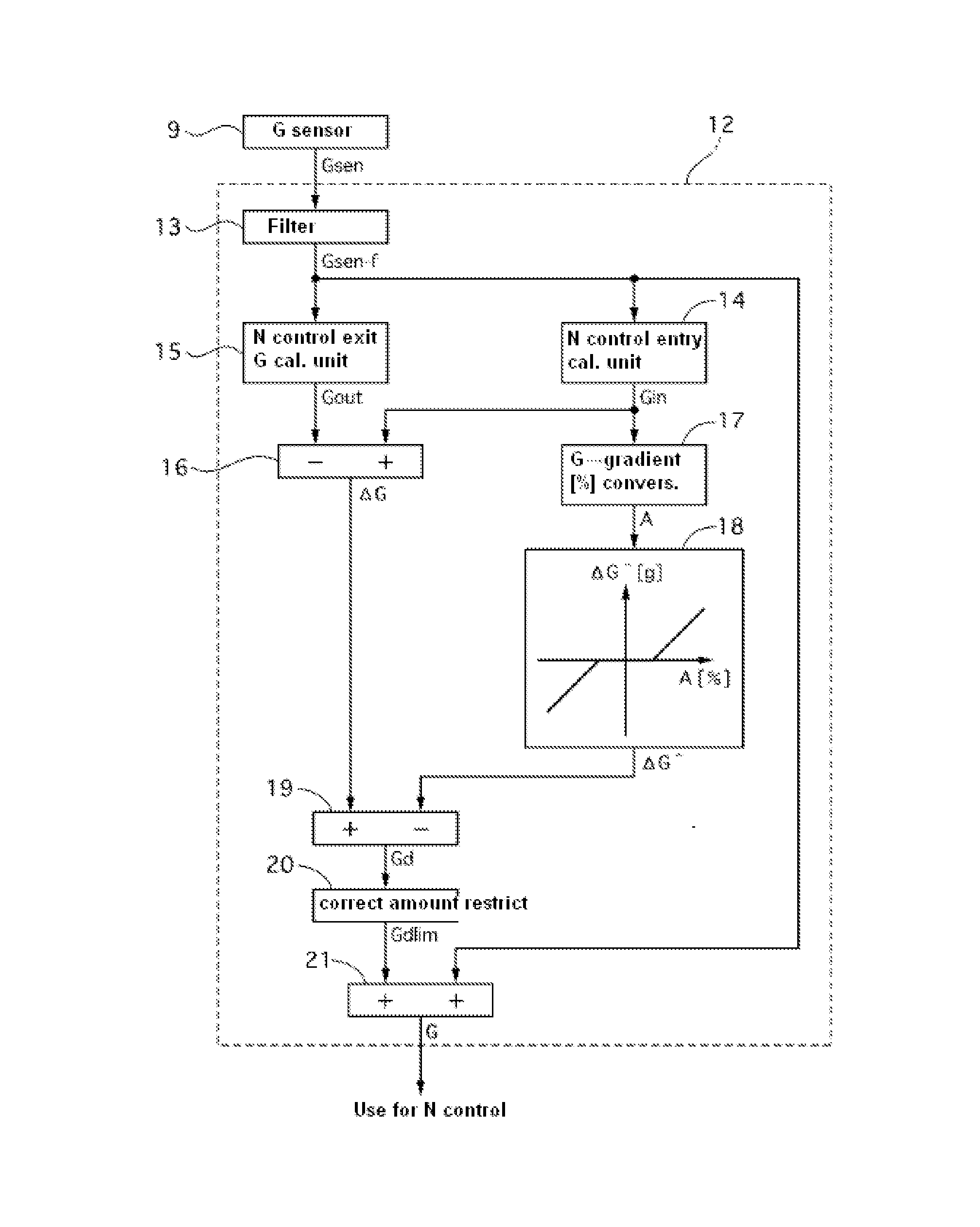
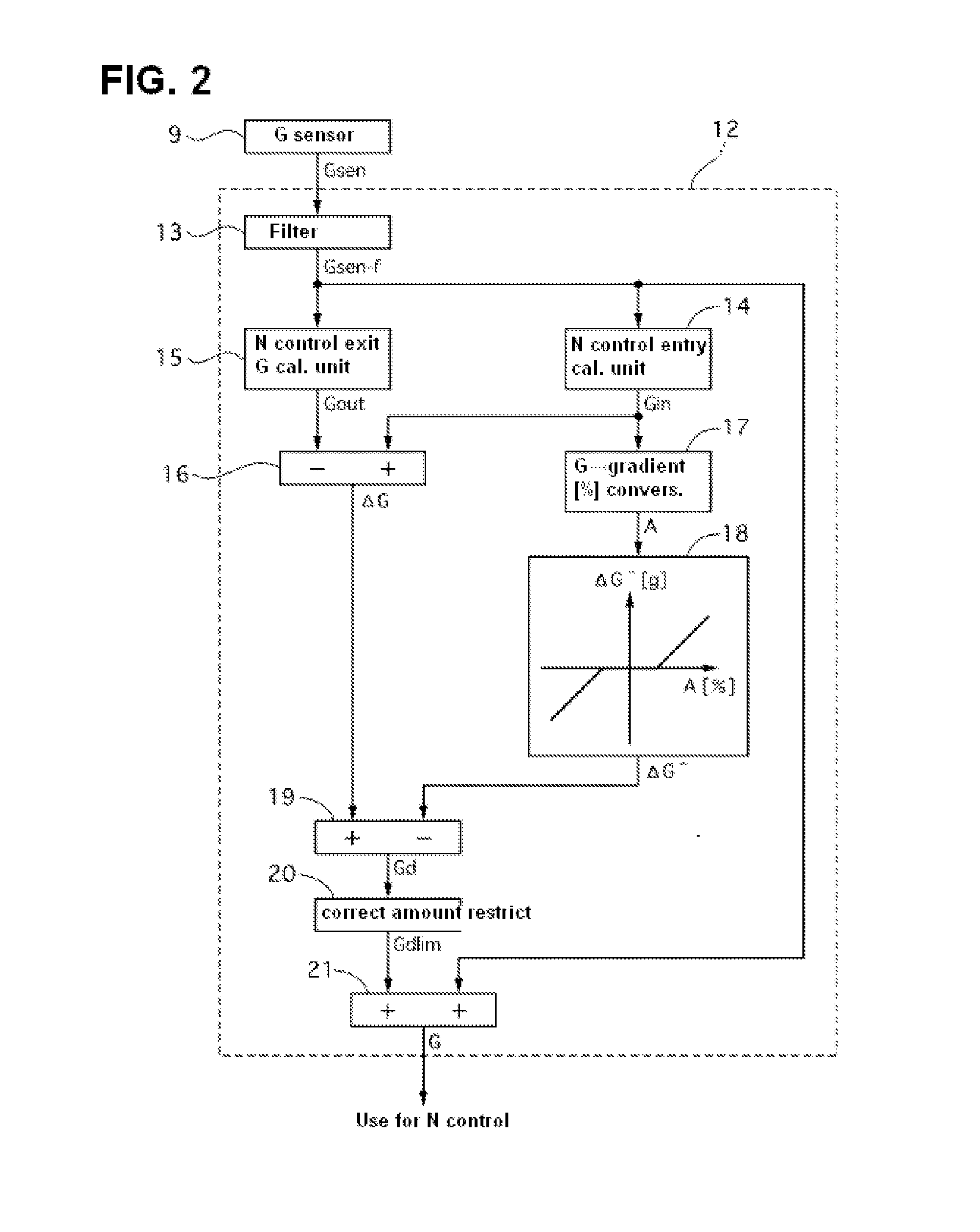
[0087]The acceleration detection device 31 of the third embodiment calculates a correction value Gd for correcting a drift error of G sensor signal Gsen based on a difference between the acceleration estimate Ĝ derivable from change in G sensor signal Gsen (i.e. N control entry acceleration Gin−N control exit acceleration Gout) and the N control entry acceleration Gin in order to perform zero point correction of G sensor signal.

[0088]When a drift error in G sensor signal is occurring due to temperature change or aging, the N control entry acceleration Gin calculated based on G sensor signal deviates from the true value by the drift error. On the other hand, the acceleration estimate Ĝ that is calculated from the difference between the N control entry acceleration Gin and the N control exit acceleration Gout is free from influence of the drift error (i.e. does not include the drift error). Thus, by taking the difference between the acceleration estimate Ĝ and the N control entry a...


PUM


Abstract

An acceleration detection device is provided with a zero point correction unit for correcting a zero point position of a sensor signal value by using the correction amount (absolute value of a correction value) based on the acceleration when the vehicle transitions from a stopped state on a sloping road to a running state. The acceleration detection device is also provided with a correction amount restriction unit for restricting the correction amount, thereby suppressing calculation of an excessive correction amount due to road surface irregularities or movement of the occupant and deterioration in correction accuracy.

Description

TECHNICAL FIELD[0001]The present disclosure relates to an acceleration detection device.BACKGROUND[0002]In the conventional acceleration detection device, based on an acceleration sensor signal of a vehicle in a stopped or stationary state and the other acceleration sensor signal in a transition state in which the vehicle transitions from the stationary state to running state, a drift error due to temperature change or aging is calculated for use in a zero point correction of the acceleration sensor. An example of such technique related to this description is disclosed in Japanese Laid-Open Patent Application Publication No. 2008-145151.BRIEF SUMMARY[0003]However, in the example described above, the acceleration signal detected during the transition from the stationary state to the running state includes a vehicle body vibration component due to an uneven road or movement of the occupant in vehicle. Thus, an excessive correction amount is inclined to be calculated, which would lead ...

Claims


Application Information

Patent Timeline
IPC IPC(8): G01P21/00
CPCB60T2230/04G01P21/00B60T2250/06
Inventor TOHTA, YUZURU
Owner NISSAN MOTOR CO LTD
Why Eureka
Try Eureka