Radome for an antenna with a concave-reflector
- Summary
- Abstract
- Description
- Claims
- Application Information
AI Technical Summary
Benefits of technology
Problems solved by technology
Method used
Image
Examples
first embodiment
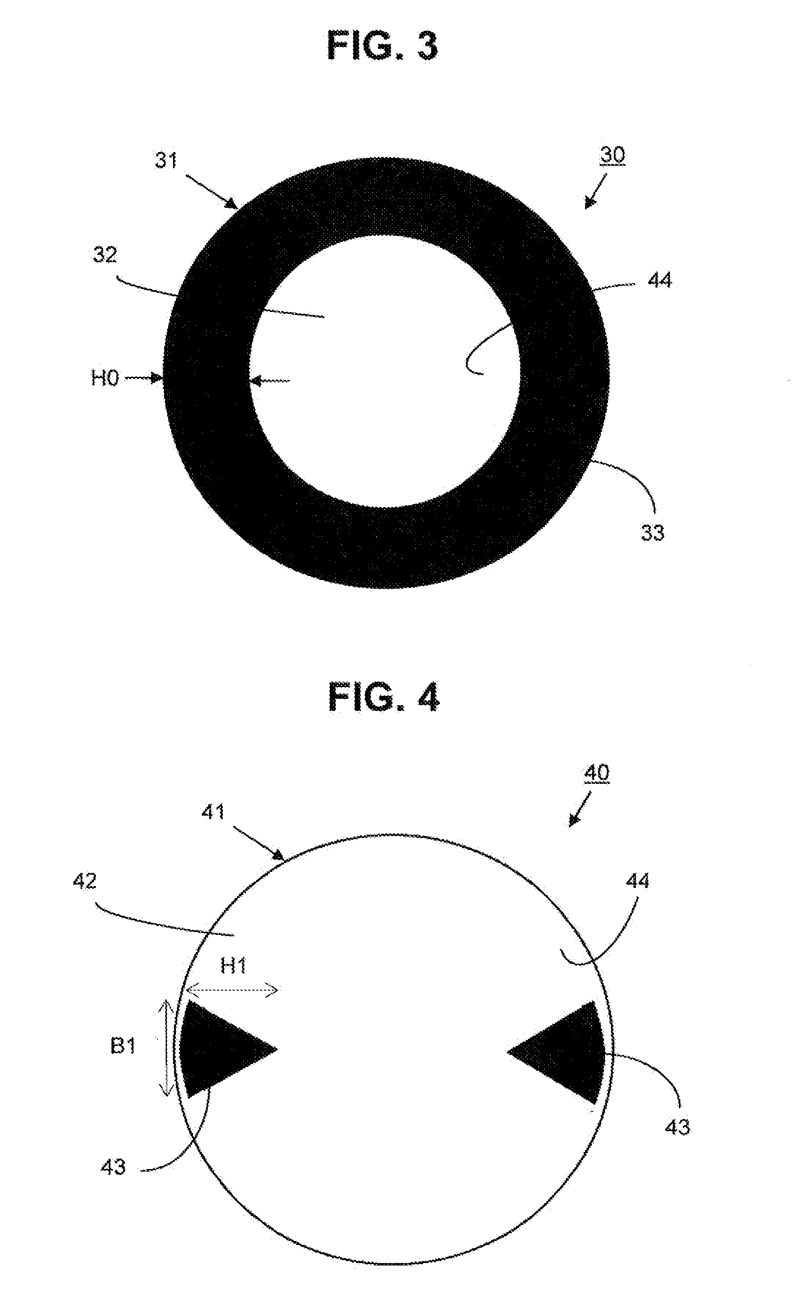
[0038]FIG. 3 depicts a microwave antenna 30 with a concave deep reflector 31 having a circular opening, protected by a radome 32 which here is a rigid flat radome. A ring 33 made of absorbent material whose width HO is disposed on the inner surface 34 of the radome 32 along the peripheral edge of the reflector 31. The reduction in spillover depends on the weights HO of the absorbing ring 33. The presence of the absorbing ring 33 makes it possible to significantly reduce spillover losses. However, in the present situation, the impact of the absorbent ring 33 on the gain of the antenna 30 will be relatively high because of the large surface area of the radome covered by the ring, which nonetheless should not exceed 25% of the total surface area, and preferably not exceed 15%. Additionally, the improvement of the radiation pattern of the antenna 30 in the horizontal plane is not preferred by this embodiment. An absorbent part has been described with the shape of a continuous solid ring...
second embodiment
[0039]We shall now consider FIG. 4 which depicts a microwave antenna 40 having a concave deep reflector 41 and low focal distance (F / D=0.2) protected by a flat rigid radome 42 that is circular in shape. Absorbent parts 43 are placed in a diametrically opposite matter, in order to improve performance in the horizontal plane (azimuth plane) by acting similarly to a shroud. The absorbent parts 43 are disposed on the inner surface 44 of the radome 41 along its periphery, which follows the edge of the reflector 41, leaving an empty area in the center of the reflector.
[0040]The absorbent parts 43 have a particular shape: Substantially triangular in this case, with the base of the absorbent part following the edge of the return, which is rounded. The reduction in spillover depends on the height H1 of the absorbent part, and the length B1 of the base of the absorbent part 43 changes the front-to-back ratio of the antenna, meaning the ratio between the radiation level of the main lobe in the...
fourth embodiment
[0046]FIG. 7 depicts a microwave antenna 70 having a circular concave reflector 71 protected by a flat rigid radome 72 that is circular in shape. Absorbent parts 73 are disposed on the inner surface 74 of the radome 72. The absorbent part 73 has substantially the shape of a triangle with height H3 and base length B3 from which areas 75 have been removed from the sides by a substantially triangular cut-out. The sides of the triangle form an inside corner. The base of the absorbent part 73 is rounded so as to match the edge shape of the circular opening of the reflector 72.
PUM
 Abstract
Description
Claims
Application Information
 - R&D
- Intellectual Property
- Life Sciences
- Materials
- Tech Scout
- Unparalleled Data Quality
- Higher Quality Content
- 60% Fewer Hallucinations
Browse by: Latest US Patents, China's latest patents, Technical Efficacy Thesaurus, Application Domain, Technology Topic, Popular Technical Reports.
© 2025 PatSnap. All rights reserved.Legal|Privacy policy|Modern Slavery Act Transparency Statement|Sitemap|About US| Contact US: help@patsnap.com


