
Patient Support Apparatus

a technology for supporting equipment and patients, which is applied in the direction of electrical steering, transportation and packaging, nursing beds, etc., can solve the problems of difficult manual wheeling of the support apparatus from one location to another, and the difficulty of a caregiver to manually wheel the support apparatus from one location to another, and the difficulty can be further exacerbated

Active Publication Date: 2016-03-31
STRYKER CORP
View PDF10 Cites 50 Cited by
  • Summary
  • Abstract
  • Description
  • Claims
  • Application Information

AI Technical Summary

Benefits of technology

The patent describes a patient support apparatus with non-driven wheels that can be adjusted to change the direction of movement. The apparatus can be controlled by a controller that determines the desired direction of movement and commands the motor to adjust the wheel orientation. The technical effect is improved mobility and flexibility for patient support during medical procedures, reducing the risk of injury and promoting patient comfort.

Problems solved by technology

While most patient support apparatuses include one or more wheels that allow the support apparatus to be wheeled from the first location to the second location, the weight and bulk of the patient support apparatus—including the weight of the patient supported thereon, can make it difficult for a caregiver to manually wheel the support apparatus from one location to another.
This can be especially difficult when there are inclines in the floors of the healthcare facility, or when there are long distances involved, or when the patient and / or the support apparatus are heavy.
This difficulty can be further exacerbated when it is desirable to maneuver the patient support apparatus into, or through, areas with little excess clearance, such as in elevators, rooms, or corridors, or when turning the patient support apparatus around a corner, or steering it past obstacles.
Despite the assistance of the powered wheel, prior art powered patient support apparatuses can still be difficult to use, and / or suffer from other disadvantages.

Method used


Image

  • Patient Support Apparatus
  • Patient Support Apparatus
  • Patient Support Apparatus

Examples


Embodiment Construction

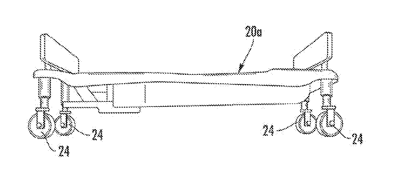
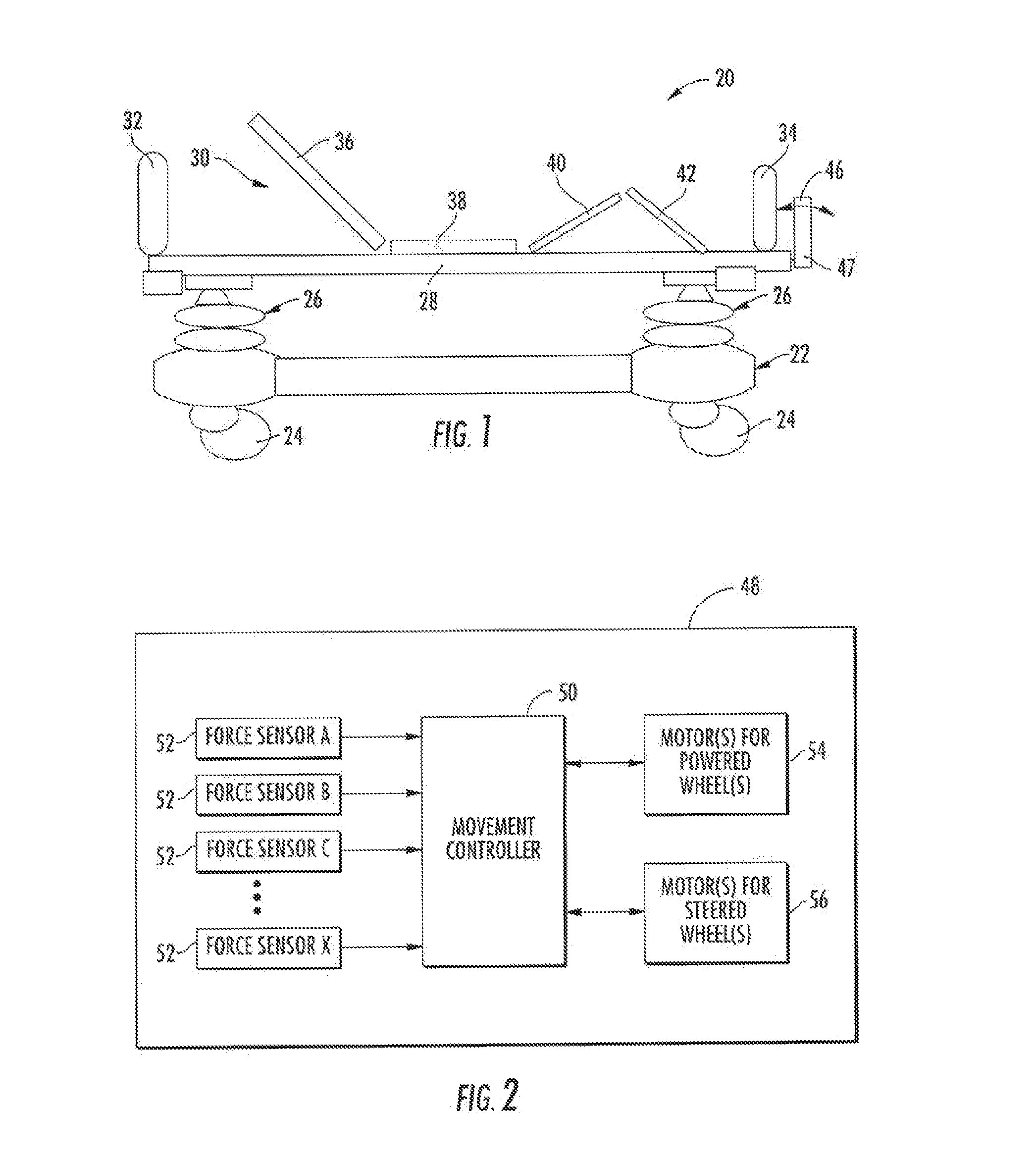
[0063]A patient support apparatus 20 according to one embodiment is shown in FIG. 1. While the particular form of patient support apparatus 20 illustrated in FIG. 1 is a bed, it will be understood that patient support apparatus 20 could, in different embodiments, be a cot, a stretcher, a gurney, or any other structure capable of supporting a patient while being transported from one place to another.

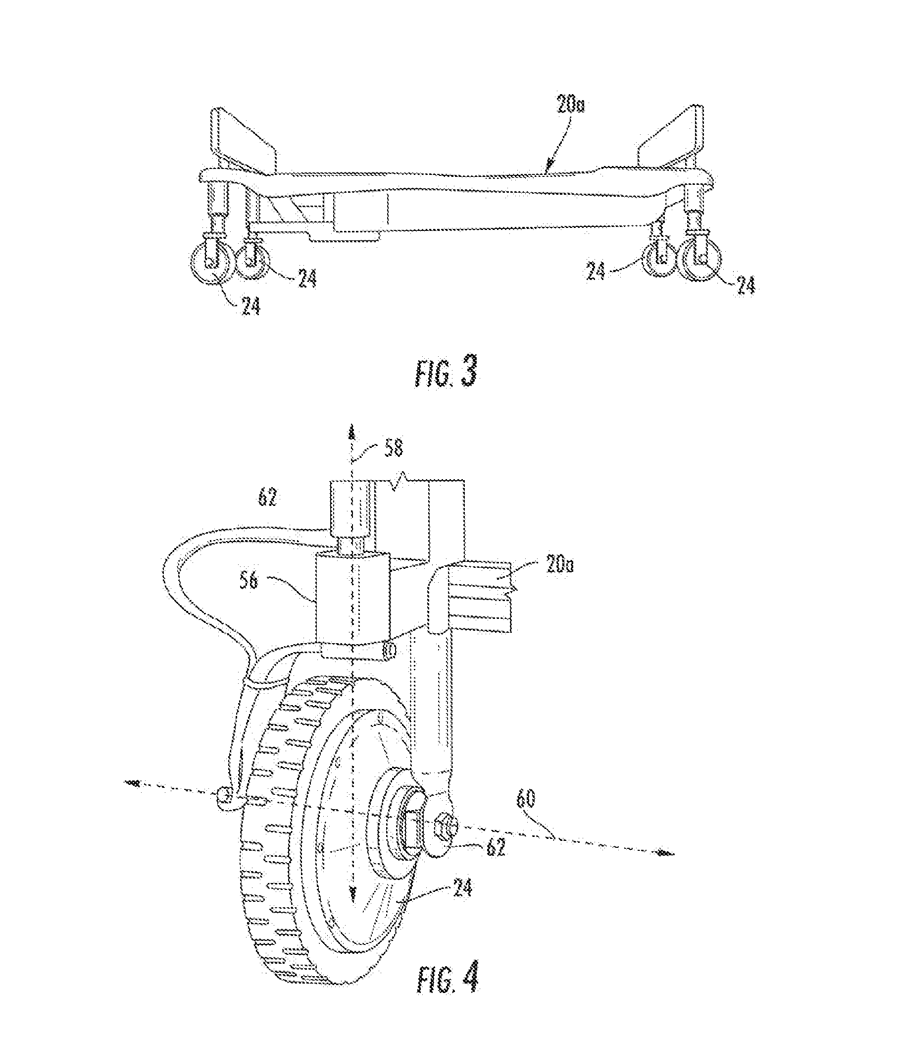
[0064]In general, patient support apparatus 20 includes a base 22 having a plurality of wheels 24, a pair of elevation adjustment mechanisms 26 supported on said base, a frame or litter 28 supported on said elevation adjustment mechanisms, and a patient support deck 30 supported on said frame. Patient support apparatus 20 further includes a headboard 32 and a footboard 34.

[0065]Base 22 includes a brake that is adapted to selectively lock and unlock wheels 24 so that, when unlocked, patient support apparatus 20 may be wheeled to different locations. Elevation adjustment mechanisms 26 are a...


PUM


Abstract

Patient support apparatuses—such as beds, cots, stretchers, or the like—include a plurality of user controls that allow a caregiver to control the steering and / or driving of one or more wheels from multiple different locations around the patient support apparatus (e.g. head end, foot end, and / or the sides). The control is carried out by force sensors that detect both an orientation of the applied forces and a magnitude of the applied forces. Translational and / or rotational movement is effectuated, depending upon the magnitude and direction of the forces, as well as the physical location of the applied force relative to a reference point on the support apparatus, such as the center. One or more object sensors may also be included in the support apparatus to assist in steering and / or navigating.

Description

CROSS-REFERENCE TO RELATED APPLICATIONS[0001]This application is a continuation-in-part of U.S. patent application Ser. No. 13 / 795,193 filed Mar. 12, 2013, which claims priority to U.S. provisional patent application No. 61 / 702,316 filed Sep. 18, 2012 by applicants Donna-Marie Robertson et al. and entitled POWERED PATIENT SUPPORT APPARATUS, the complete disclosures of both of these applications being hereby incorporated herein by reference. This application also claims priority to U.S. provisional patent application No. 62 / 247,396 filed Oct. 28, 2015 entitled SYSTEMS AND METHODS FOR FACILITATING MOVEMENT OF A PATIENT TRANSPORT APPARATUS, the complete disclosure of which is hereby incorporated herein by reference.BACKGROUND OF THE INVENTION[0002]The present invention relates to patient support apparatuses—such as, but not limited to, beds, stretchers, cots, operating tables, and the like—and more particularly to patient support apparatuses that have at least one wheel to assist in th...

Claims


Application Information

Patent Timeline
IPC IPC(8): A61G1/02B62D5/04
CPCA61G1/0281B62D5/0457A61G1/0275A61G1/0287A61G1/0243A61G7/0528A61G7/08A61G2203/22A61G2203/32A61G2203/40A61G2205/60
Inventor DELUCA, RICHARD, THOMASDERENNE, RICHARD, A.
Owner STRYKER CORP
Features
  • Generate Ideas
  • Intellectual Property
  • Life Sciences
  • Materials
  • Tech Scout
  • Unparalleled Data Quality
  • Higher Quality Content
  • 60% Fewer Hallucinations
Learn More