Compressible plastic container with base cup

a plastic container and base cup technology, applied in the field of containers, can solve problems such as preventing the changeover to other containers, and achieve the effects of reducing packaging, reducing costs, and increasing market acceptan

Active Publication Date: 2016-03-31
KRONES AG
View PDF42 Cites 11 Cited by
  • Summary
  • Abstract
  • Description
  • Claims
  • Application Information

AI Technical Summary

Benefits of technology

[0031]A further advantage of a tap system to be used is that, when the base cup and the contact segment or the die respectively with the container are changed a change of format is also possible. Thus not only different volumes can be tapped, but also different shapes can be used in order to enable a certain freedom for individual container configuration. Thus the so-called branding is likewise possible. If shaping parts are attached to the container at both ends, the container is perceived even more as a keg, resulting in a higher market acceptance. The greatest advantage lies in the cost saving, which not only results from the reduced packaging but costs can also be saved in the tap device.

Problems solved by technology

Replacement of these shaping parts is possible but only with relative difficulty, which in particular also significantly impedes a changeover to other containers.
Such careless handling could for example be the hard placing of containers on a floor or the lugging of a container (often weighing up to 20 kilos) over the floor.

Method used


Image

  • Compressible plastic container with base cup
  • Compressible plastic container with base cup
  • Compressible plastic container with base cup

Examples


Embodiment Construction

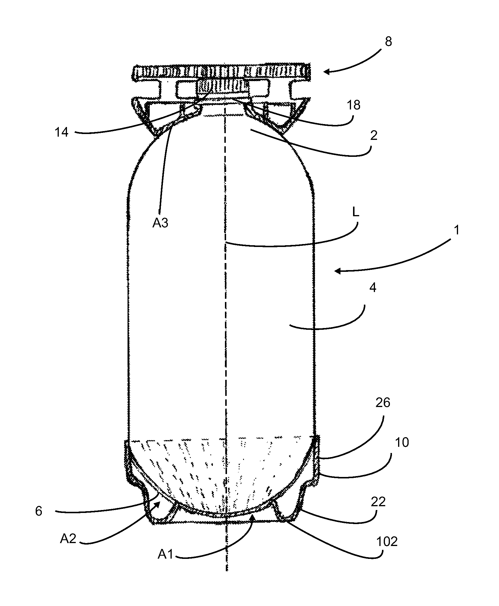
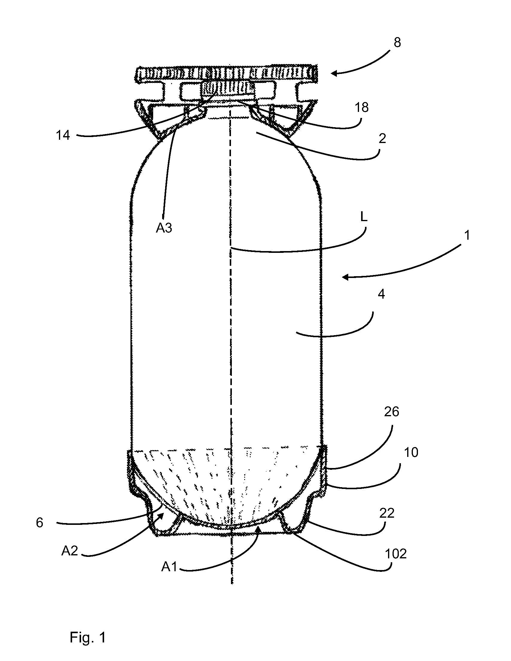
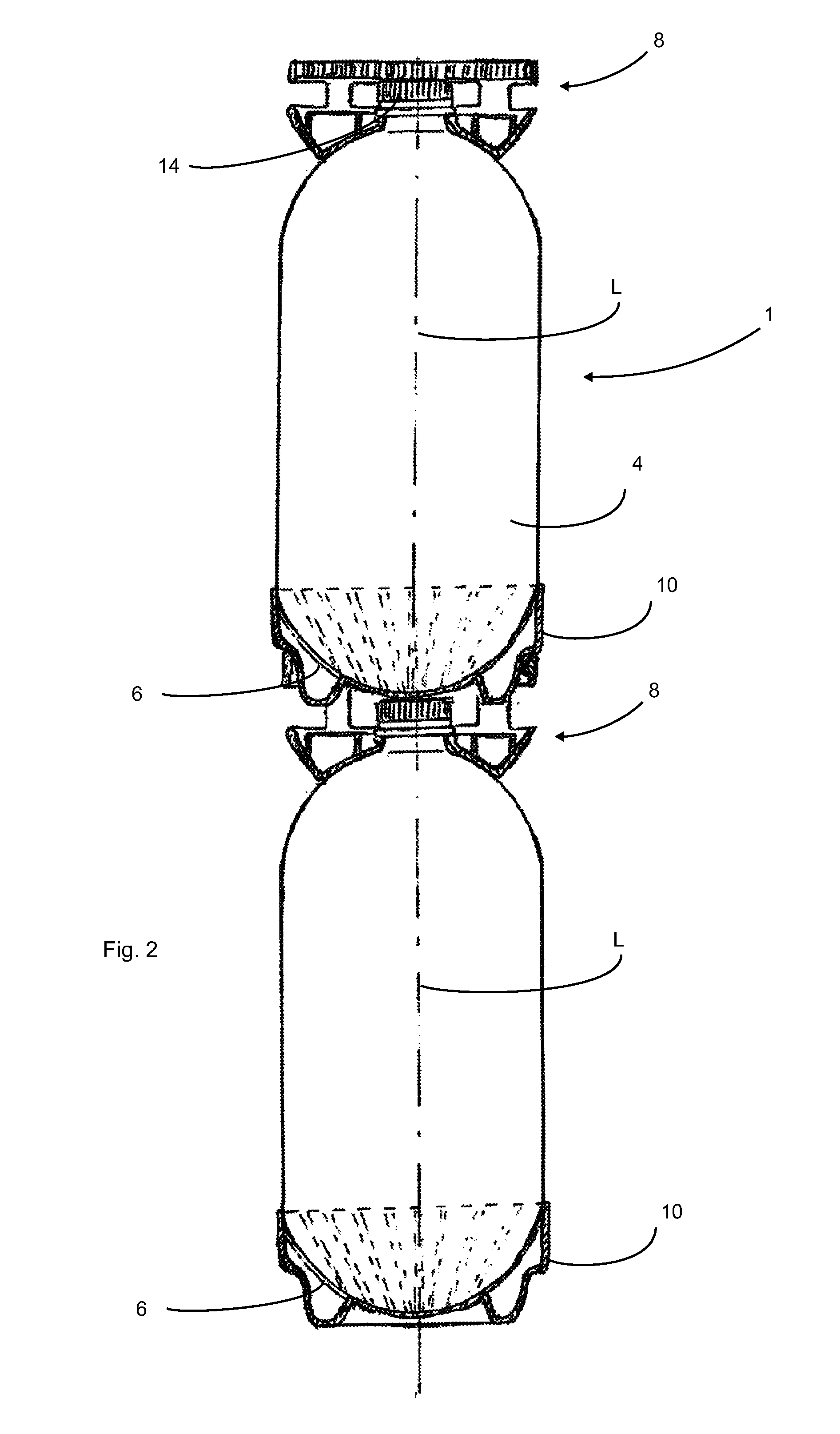
[0043]FIG. 1 shows a side view of a container 1 according to embodiments of the invention. This container 1 has a base region 6 adjoined by a main body 4. This main body 4 in turn adjoins a mouth or shoulder region 2 respectively. In this case the majority of a liquid in the container is located in the region surrounded by the main body of the container. The reference numeral L designates a longitudinal direction of the container along which the container 1 is also compressed.

[0044]The reference numeral 10 designates a base cup which is disposed on the base region. In this case it can be seen that in a region A1 this base cup lies directly in contact on the base region 6 and in a further region A2 is distanced from the base region. In this case the region A1, along which the base cup 10 lies in contact on the base region 6, is of rotationally symmetrical or circular construction respectively (when viewed in a projection along the longitudinal direction L). Furthermore, however, the ...


PUM


Abstract

A container, in particular a plastic container with a base region, a main body which adjoins this base region and is suitable to receive a volume of liquid, and with a mouth region, wherein the container can be compressed along its longitudinal direction for the removal of liquid located in the container is provided. On the base region a base cup is disposed which forms a base surface for the container and which when the container is compressed can also serve as a die element and/or die counter-element for compressing the container.

Description

CROSS-REFERENCE TO RELATED APPLICATIONS[0001]This application claims priority to German Application No. 10 2014 113 915.1, having a filing date of Sep. 25, 2014, the entire contents of which are hereby incorporated by reference.FIELD OF TECHNOLOGY[0002]The following relates to a container and in particular a plastic container.BACKGROUND[0003]Numerous such plastic containers are known. These plastic containers have different filling volumes. Furthermore compressible containers of which the contents can be removed by compression of the container are known. In such a tap system of the applicant PET bottles (BEVkeg) are emptied by deforming the container wall and the container shoulders. For this targeted deformation, in which in particular a mouth region of the containers is pushed into a base region of the containers, shaping parts (in particular dies) which are specially adapted to the container are used in the tap system. These shaping parts are designed on one side as a die, in ord...

Claims


Application Information

Patent Timeline
Patent Type & Authority Applications(United States)
IPC IPC(8): B65D35/08B65D21/02B65D25/28
CPCB65D35/08B65D25/28B65D21/0209B65D21/023B65D23/001B65D1/0292
Inventor MEINZINGER, RUPERT
Owner KRONES AG
Why Eureka
Try Eureka