Vaginal wall incision instrument

a technology of incision instrument and vaginal wall, which is applied in the field of vaginal wall incision instrument, can solve the problems of difficult straight separation along the separating lin

Active Publication Date: 2016-04-07
OLYMPUS CORP
View PDF5 Cites 13 Cited by
  • Summary
  • Abstract
  • Description
  • Claims
  • Application Information

AI Technical Summary

Problems solved by technology

For this reason, straight separation along the separating line is not easy without tilting the uterus using the uterine manipulator.

Method used


Image

  • Vaginal wall incision instrument
  • Vaginal wall incision instrument
  • Vaginal wall incision instrument

Examples


first embodiment

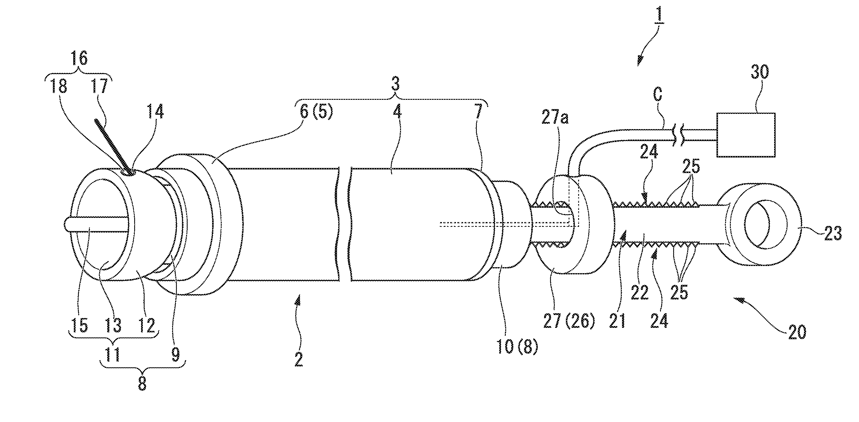
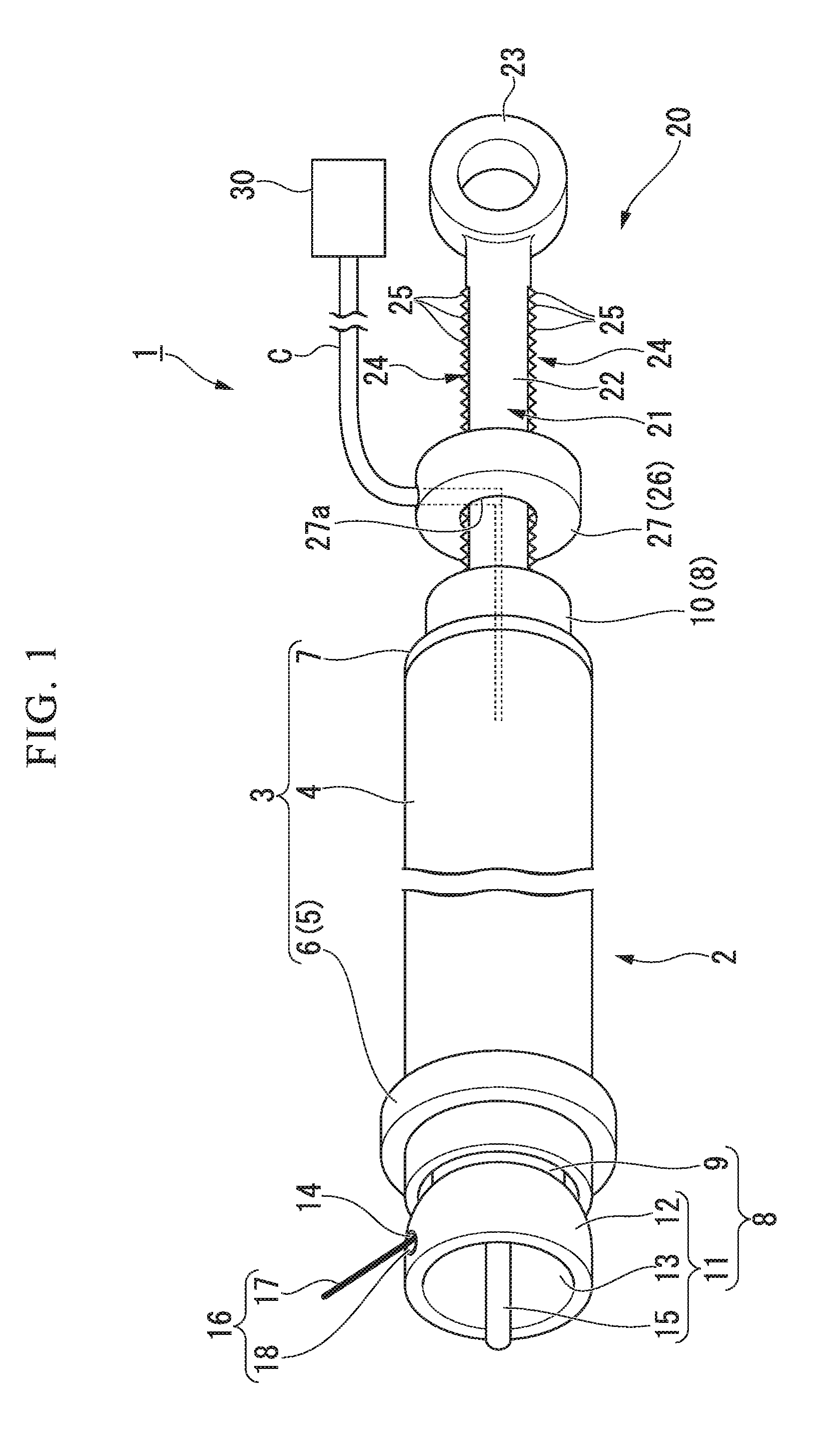
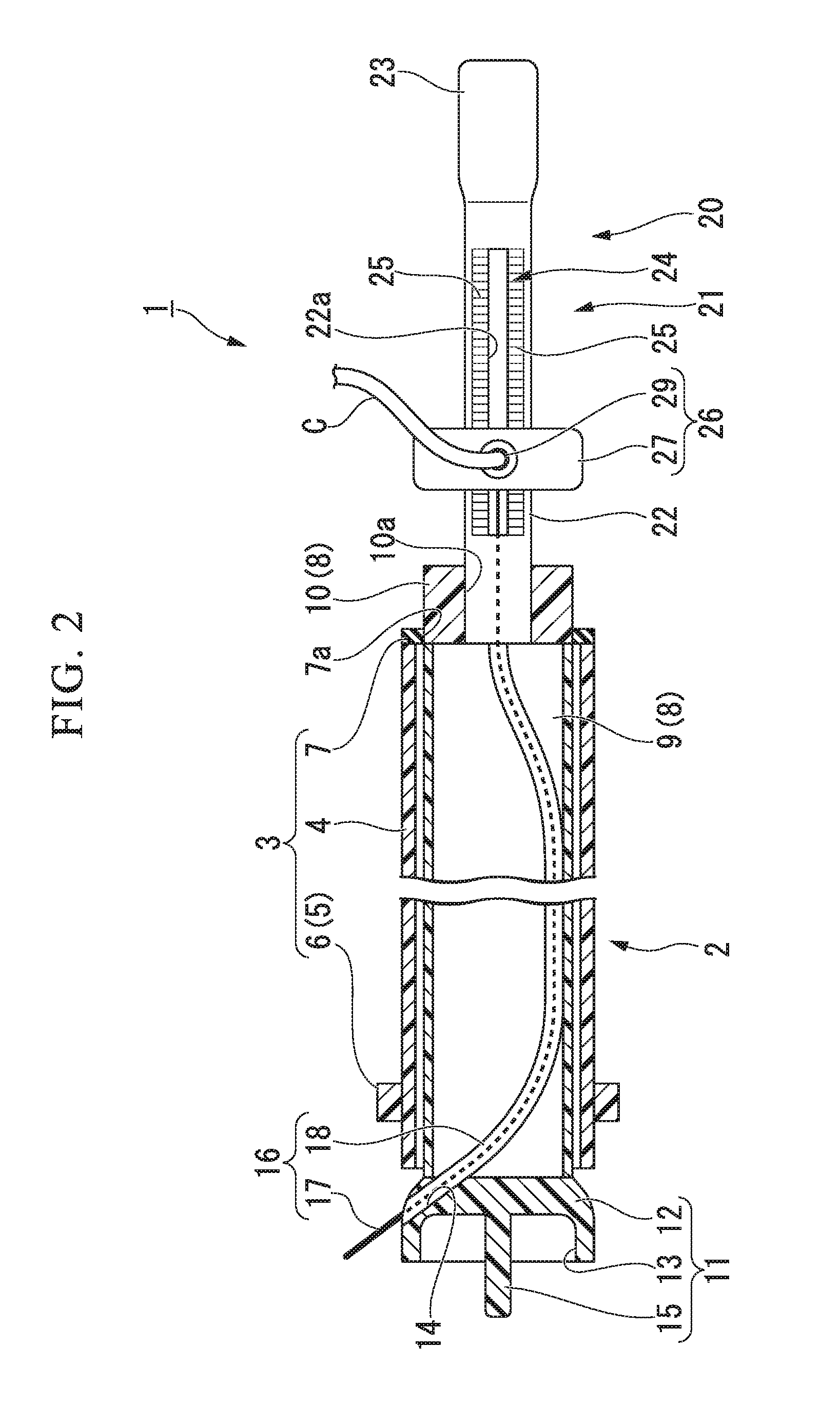
[0051]A first embodiment of the present invention will be described. FIG. 1 is a general view of a vaginal wall incision instrument 1 according to the present embodiment. FIG. 2 is a partial cross-sectional view of the vaginal wall incision instrument 1 according to the present embodiment. FIG. 3 is a cross-sectional view of an operating portion 20 in the vaginal wall incision instrument 1 according to the present embodiment.

[0052]The vaginal wall incision instrument 1 illustrated in FIG. 1 is a medical instrument that can be used to separate a uterus from a vagina in a total laparoscopic hysterectomy and a laparoscopic supracervical hysterectomy.

[0053]As illustrated in FIG. 1, the vaginal wall incision instrument 1 has a substantially bar shape as a whole. The vaginal wall incision instrument 1 includes a main body portion 2, an incision portion 16, and the operating portion 20.

[0054]As illustrated in FIGS. 1 and 2, the main body portion 2 has a substantially bar shape as a whole. ...

second embodiment

[0113]Next, a second embodiment of the present invention will be described. In embodiments to be described below, components having the same functions or structures as those in the vaginal wall incision instrument 1 according to the above-described first embodiment are denoted by the same reference numerals as in the first embodiment, and redundant descriptions thereof will be omitted.

[0114]FIG. 8 is a perspective view of a part of a vaginal wall incision instrument 1A according to the present embodiment. FIG. 9 is a cross-sectional view of a distal portion of the vaginal wall incision instrument 1A according to the present embodiment.

[0115]As illustrated in FIGS. 8 and 9, the vaginal wall incision instrument 1A according to the present embodiment includes a main body portion 2A whose configuration is different from the main body portion 2 described in the first embodiment.

[0116]As illustrated in FIG. 9, the main body portion 2A includes an exterior portion 3A and an interior portio...

third embodiment

[0121]Next, a third embodiment of the present invention will be described. FIG. 10 is a perspective view of a main body portion of a vaginal wall incision instrument 1B according to the present embodiment. FIG. 11 is a perspective view of an outer tubular member 4B of the vaginal wall incision instrument 1B according to the present embodiment. FIG. 12 is a perspective view of an intermediate tubular member 36 of the vaginal wall incision instrument 1B according to the present embodiment. FIG. 13 is a perspective view of an inner tubular member 9B of the vaginal wall incision instrument 1B according to the present embodiment. FIG. 14 is a perspective view of an incision portion 16B of the vaginal wall incision instrument 1B according to the present embodiment. FIG. 15 is a cross-sectional view of the inner tubular member 9B of the vaginal wall incision instrument 1B according to the present embodiment. FIG. 16 is a diagram describing an operation of the vaginal wall incision instrume...


PUM


Abstract

A vaginal wall incision instrument includes a main body portion that is capable of being inserted into a vaginal canal; an incision portion that protrudes from a distal portion of the main body portion in a direction intersecting a center line of the vaginal canal and is formed by a conductive material; and an operating portion, wherein the main body portion includes an exterior portion and an interior portion, wherein the interior portion includes a contact portion, wherein a guide hole is configured on the interior portion, wherein the guide hole is capable of guiding the conductive member in a direction toward a boundary between the uterine cervix and the vaginal canal, and wherein the incision portion separates the vaginal canal along a circumference whose center is the center line of rotation by rotating the interior portion about the center line of rotation with respect to the exterior portion.

Description

[0001]This application is a continuation application based on a PCT International Application No. PCT / JP2014 / 080353, filed on Nov. 17, 2014, whose priority is claimed on Japanese Patent Application No. 2014-003132 filed on Jan. 10, 2014. The content of both the PCT International Application and the Japanese Patent Application are incorporated herein by reference.BACKGROUND OF THE INVENTION[0002]1. Field of the Invention[0003]The present invention relates to a vaginal wall incision instrument.[0004]2. Description of Related Art[0005]In recent years, as a procedure for incising a uterus, a total laparoscopic hysterectomy and a laparoscopic supracervical hysterectomy have been known. The total laparoscopic hysterectomy and the laparoscopic supracervical hysterectomy are procedures in which a laparoscope, a uterine manipulator, and a dissection instrument need to be used. That is, in the total laparoscopic hysterectomy and the laparoscopic supracervical hysterectomy, it is necessary to ...

Claims


Application Information

Patent Timeline
Patent Type & Authority Applications(United States)
IPC IPC(8): A61B18/14
CPCA61B18/1485A61B2018/00559A61B2018/00601A61B2018/00279A61B2018/00077A61B2018/00083A61B2018/00208A61B2018/144A61B17/42A61B2017/4225A61B2018/1425A61B2018/1475A61B2018/00196
Inventor MOTAI, KOSUKETAKEI, YUSUKE
Owner OLYMPUS CORP
Why Eureka
Try Eureka