Off-road rolling film vision system

a vision system and film technology, applied in the field of protective hardware, can solve problems such as dirt and mud in the back of the vehicl

Inactive Publication Date: 2016-04-07
KULIK MARK
View PDF1 Cites 2 Cited by
  • Summary
  • Abstract
  • Description
  • Claims
  • Application Information

AI Technical Summary

Benefits of technology

[0007]Embodiments are directed to an OFF-ROAD ROLLING FILM VISION SYSTEM (100) for giving off-road riders a hands-free method of keeping their goggles or face shield clear of dust, mud and other debris by having a transparent film moving across the goggles or face shield to collect and remove the dust, mud and other debris.

Problems solved by technology

During the run, the vehicles cast up dirt and mud.

Method used


Image

  • Off-road rolling film vision system
  • Off-road rolling film vision system
  • Off-road rolling film vision system

Examples


Embodiment Construction

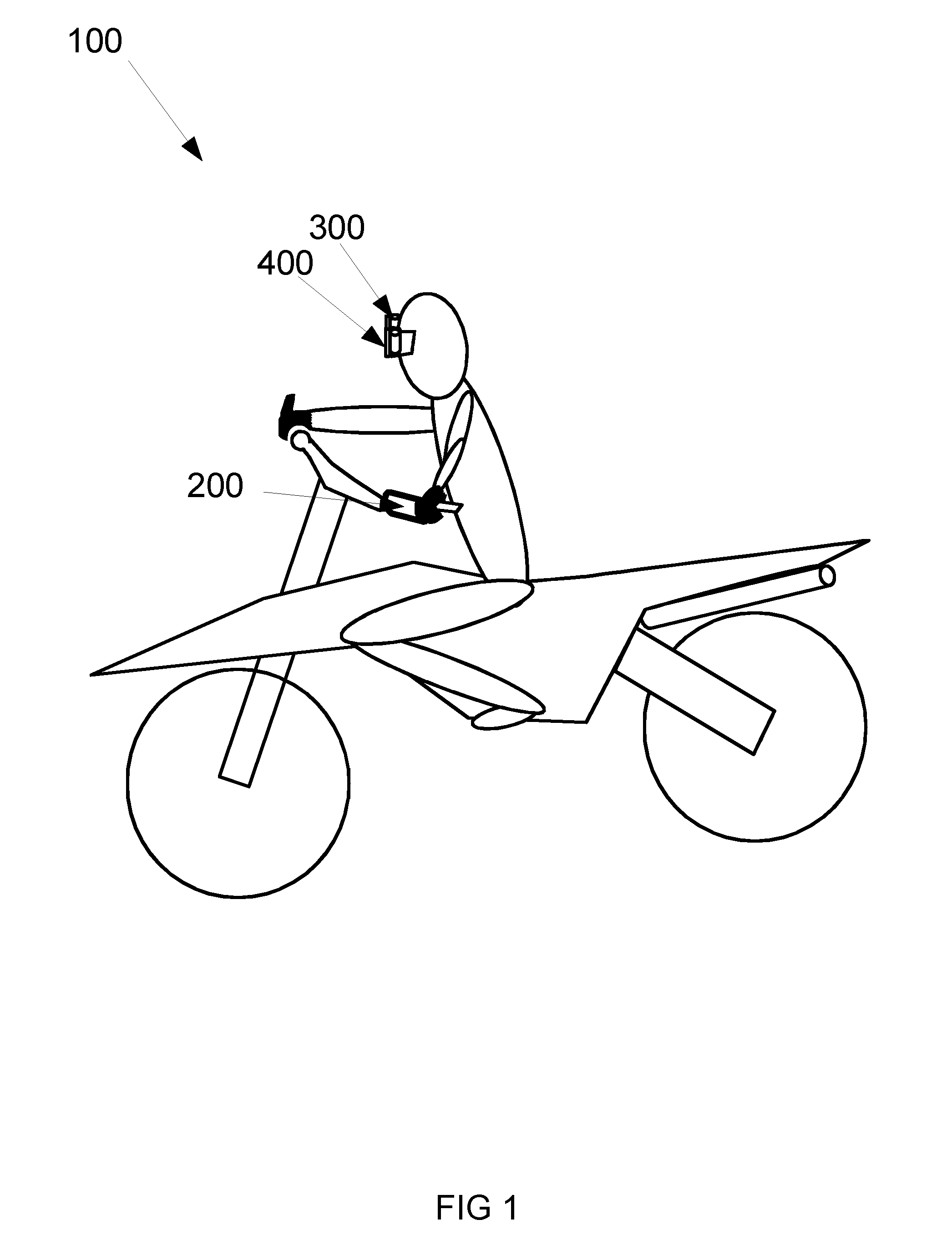
[0032]FIG. 1 shows an exemplary OFF-ROAD ROLLING FILM VISION SYSTEM (100) for giving off-road racers and other off-road fans a hands-free method of keeping their goggles or face shield clear of dust, mud and other debris by having a transparent film moving across the goggles or face shield to collect and remove the dust, mud and other debris. The exemplary OFF-ROAD ROLLING FILM VISION SYSTEM (100) comprises a Controller Module (200), a Takeup Module (300), and a Rollout Module (400). Details of the exemplary OFF-ROAD ROLLING FILM VISION SYSTEM (100) with a preferred and optional embodiments are subsequently described.

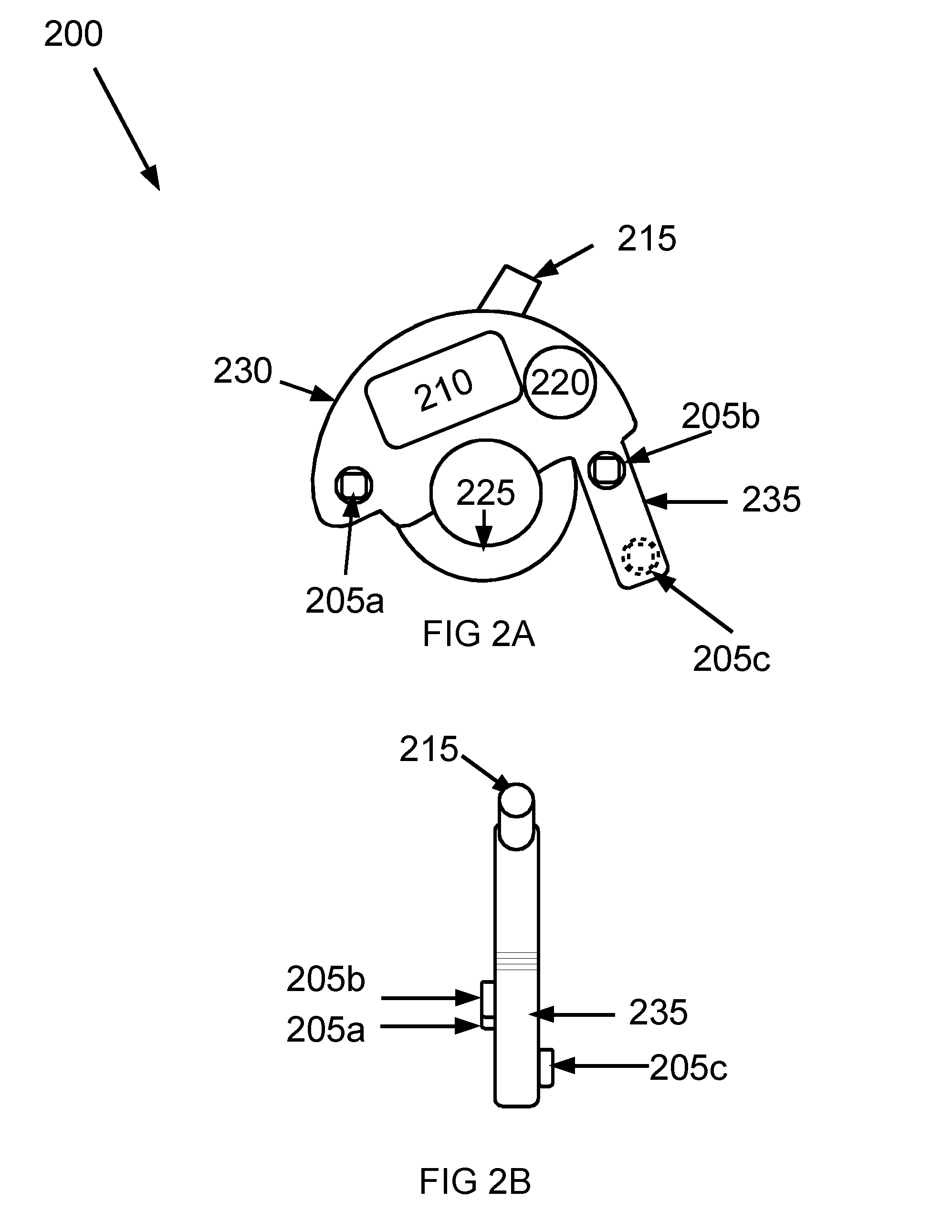
[0033]FIGS. 2A and 2B shows an embodiment of the Controller Module (200). The Controller Module (200) embodiment shown comprises a Command Input (205), a Controller Process Module (210), a Command Transmitter (215), a Power Supply (220), a Vehicle Attachment (225), a Housing (230) and a Controller Extension (235). Some embodiments comprise a Clothing Attachment (not sho...


PUM

PropertyMeasurementUnit
distanceaaaaaaaaaa
transparentaaaaaaaaaa
Transparentaaaaaaaaaa

Abstract

Disclosed is an Off-Road Rolling Film Vision System comprising a Controller Module (200), a Takeup Module (300), and a Rollout Module (400). The Controller Module (200) comprises a Command Input (205), a Controller Process Module (210), a Command Transmitter (215), and a Power Supply (220). The Controller Module (200) is configured to remotely control a Motor (325) in the Takeup Module (300). The Command Input (205) comprises at least one Button configured to accept a knuckle bump for controlling a Motor (325) in the Takeup Module (300) when the Controller Module (200) is attached to a handlebar of an off-road vehicle. The at least one Button configured to accept a knuckle bump may be configured to be adjacent to a user's metacarpophalangeal index finger joint. The at least one Button configured to accept a knuckle bump may be configured to be adjacent to a user's metacarpophalangeal thumb joint. The Takeup Module (300) comprises a Motor Compartment (305), a Takeup Spool Compartment (310), a Takeup Spool Gear Compartment (315), a Takeup Film Window (320), a Motor (325), a Motor Gearbox (330), and at least one Takeup Spool Gear (340). The Takeup Module (300) may further comprise a Takeup Spool Window (350) configured to provide a view of a Takeup Spool (345) within the Takeup Module (300). Also disclosed is a Takeup Spool (500) comprising a Spool Alignment Tab Wheel (505), a Spool Ribbed Shaft (510), a Rib Quarter Section Cutout (515), a Spool Alignment Slot Wheel (525), a Spool Alignment Tab (530), a Spool Alignment Slot (535), a Plurality of Wheel Cutouts (540), and a Plurality of Wheel Slots (545). Also disclosed is a method for maintaining clear vision with goggles comprising receiving a command input via a knuckle bump, transmitting a designated signal to a module comprising a Motor and a Takeup Spool, activating the Motor to cause the Takeup Spool to rotate, and winding a Transparent Film a designated distance over goggles.

Description

CROSS-REFERENCE TO RELATED APPLICATION[0001]This application is a divisional of U.S. Non-Provisional patent application Ser. No. 14 / 543,794 filed Nov. 17, 2014 titled OFF-ROAD ROLLING FILM VISION SYSTEM, which claims the benefit of priority of U.S. Provisional Patent Application 61 / 907,532 filed Nov. 22, 2013 and titled “AUTO ROLLING FILM SYSTEM,” the disclosure of which is incorporated by reference. This application is related to four design patent applications filed Nov. 17, 2014 and by the same inventor and titled “SPOOL FOR OFF-ROAD ROLLING FILM VISION SYSTEM”, “TAKEUP MODULE for OFF-ROAD ROLLING FILM VISION SYSTEM”, “ROLLOUT MODULE FOR OFF-ROAD ROLLING FILM VISION SYSTEM” and “CONTROLLER FOR OFF-ROAD ROLLING FILM VISION SYSTEM.”STATEMENT REGARDING FEDERALLY SPONSORED RESEARCH OR DEVELOPMENT[0002]Not ApplicableBACKGROUND OF THE INVENTION[0003]1. Field of Invention[0004]The invention relates generally to the field of protective hardware for off-road riding and racing and other of...

Claims


Application Information

Patent Timeline
Patent Type & Authority Applications(United States)
IPC IPC(8): B65H75/14B65H16/06B65H18/02A61F9/02
CPCB65H75/14A61F9/025B65H2701/19B65H18/028B65H16/06B65H18/103B65H2301/4493B65H2557/11A42B3/26B65H18/00
Inventor KULIK, MARK
Owner KULIK MARK
Why Eureka
Try Eureka