Synchronous rectification circuit having burst mode controller and controlling method thereof

a synchronous rectification circuit and controller technology, applied in the direction of dc-dc conversion, climate sustainability, power conversion systems, etc., can solve the problems of conduction loss, switch loss, and constant loss, so as to reduce loss and increase the light-load efficiency of the resonant circuit

Active Publication Date: 2009-10-01
DELTA ELECTRONICS INC
View PDF4 Cites 126 Cited by
  • Summary
  • Abstract
  • Description
  • Claims
  • Application Information

AI Technical Summary

Benefits of technology

[0009]It is therefore an object of the present invention to provide an operating mode of a synchronous rectification circuit having a burst mode controller so as to decrease the loss, raise the light-load efficiency of the resonant circuit to its extreme limit, and apply to an LLC resonant converter circuit and a buck converter circuit.
[0012]Preferably, the first synchronous rectifier includes a body diode, and due to delaying one of the non-integer operating period and the at least one operating period to generate the synchronous rectification driving signal of the first synchronous rectifier counting from the beginning of the first pulse of the driving signal of the first switch during the working time of the burst period, the first synchronous rectifier operating under a burst mode is on after the body diode is conducting to avoid the energy transferring back so as to relatively decrease a loss of the circuit.
[0018]Preferably, the PWM converter is a buck converter having an inductor, and due to turning off the synchronous rectification driving signal of the first synchronous rectifier by one of the non-integer operating period and the at least one operating period ahead of the ending of the last operating period of the driving signal of the first switch during the working time of the burst period, the first synchronous rectifier is turned off when a current flowing through the inductor is reversed so as to avoid an energy transferring back when the first synchronous rectifier is switching.

Problems solved by technology

However, the light-load efficiency of the resonant converters still cannot meet the requirements yet.
It is because that the resonant converters need a magnetizing current having a specific value to realize a soft-switching while under the light load condition, this will cause certain constant losses such as the conduction loss and the switch loss, and these losses possess a higher ratio when they are under the light-load condition than they are under the heavy-load condition.
And all these increase the losses of the circuit.
Thus, without any improvements, the light-load efficiency of the above-mentioned resonant circuit is much lower than the heavy-load efficiency of the same.
But under this burst mode control method, the driving of the synchronous rectifiers in the secondary side is generally not optimized and this will influence the circuit's efficiency.
As shown in FIG. 3, the output voltage Vo appears a dramatically drop in t0-t1 due to the energy's transferring back, and this results in a large iLr in the next operating period and the increasing power loss.
But the drawback is the conduction loss is increased since the forward voltage drop of the body diode is much larger than that of the synchronous rectifier.

Method used


Image

  • Synchronous rectification circuit having burst mode controller and controlling method thereof
  • Synchronous rectification circuit having burst mode controller and controlling method thereof
  • Synchronous rectification circuit having burst mode controller and controlling method thereof

Examples


Embodiment Construction

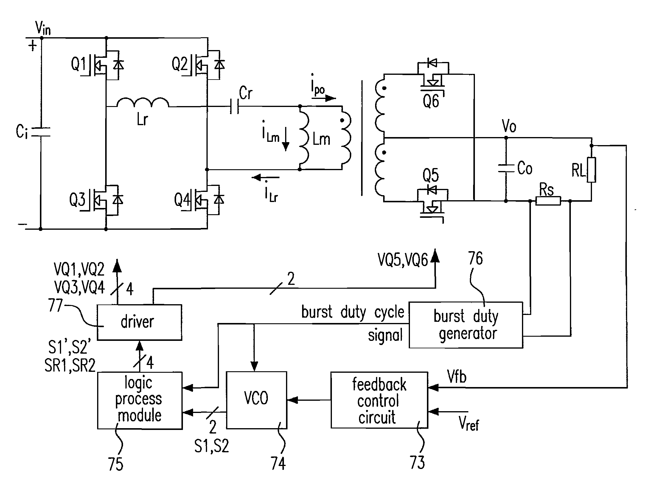
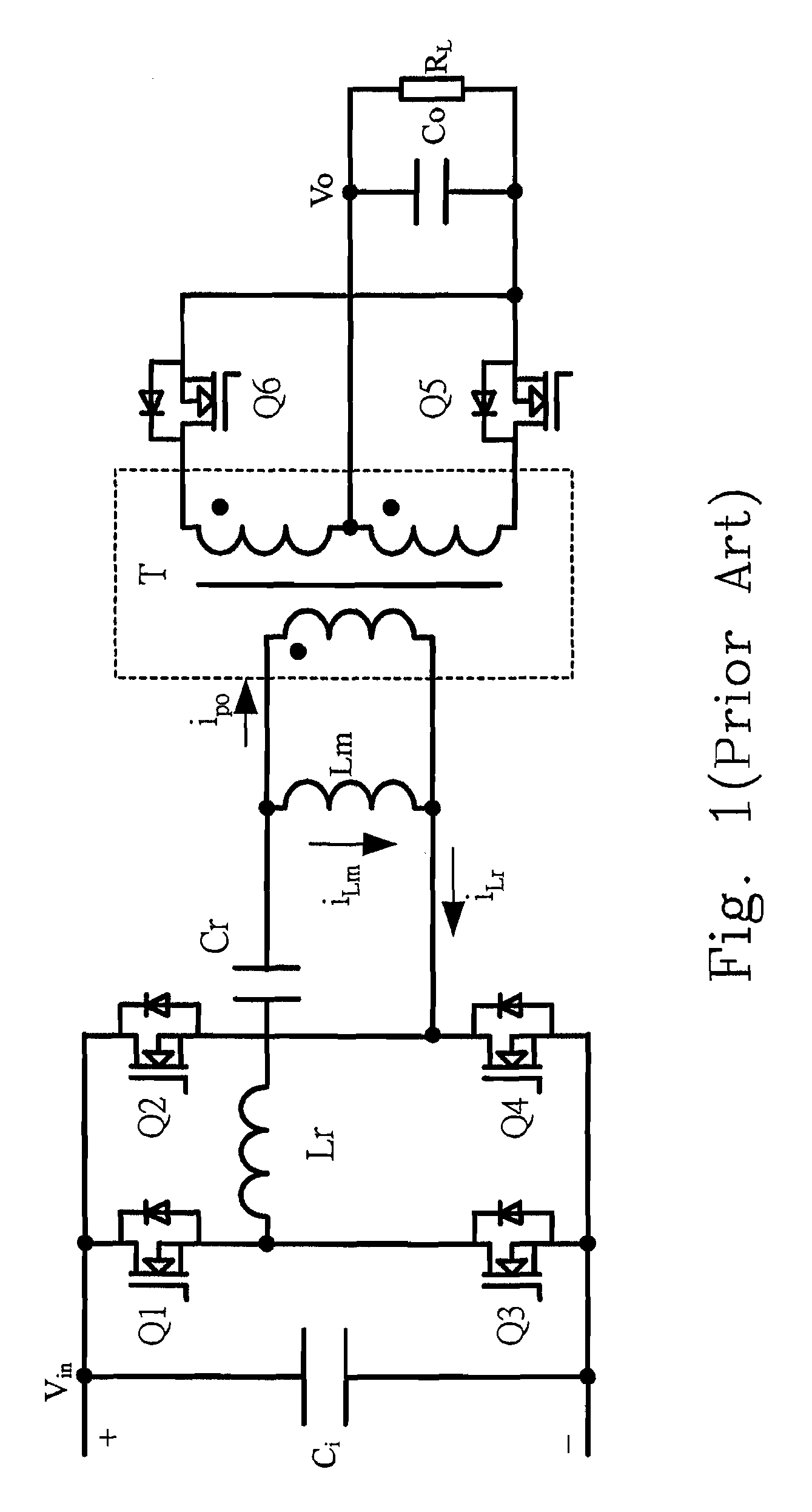
[0042]The controlling method proposed in the present invention optimizes the driving signals of the synchronous rectifiers of the resonant circuit when operating under the burst mode control. At the beginning of one burst period, the current of the resonant inductor Lr, iLr, and the voltage of the resonant capacitor Cr, Vcr, are almost equal to zero (see FIG. 1) due to the oscillation the resonant tank has experienced in the breaking time of the previous burst period. At the beginning of the burst period, due to the switching of the primary switches Q1-Q4 (see FIG. 1 also), the resonant tank receives the voltage source Vin and the equivalent circuits are shown in FIGS. 4(a)-4(b). FIG. 4(a) shows an equivalent circuit of an LLC series resonant converter at the beginning of a burst period according to the present invention, and FIG. 4(b) shows an equivalent circuit of an LLC parallel resonant converter at the beginning of a burst period according to the present invention. In FIGS. 4(a...


PUM


Abstract

The configuration of a synchronous rectification circuit and a controlling method thereof are provided. The proposed circuit includes a converter including a first switch and a first synchronous rectifier, and a burst mode controller including a logic process module performing one of functions of delaying one of a non-integer and at least one operating periods to generate a synchronous rectification driving signal of the first synchronous rectifier counting from a beginning of a first pulse of a driving signal of the first switch during a working time of a burst period, and turning off the synchronous rectification driving signal of the first synchronous rectifier by one of the non-integer operating period and the at least one operating period ahead of an ending of a last operating period of the driving signal of the first switch during the working time of the burst period.

Description

FIELD OF THE INVENTION[0001]The present invention relates to the operating mode of a synchronous rectification circuit having a burst mode controller. More specifically, this invention relates to an LLC series resonant converter circuit having a burst mode controller and a buck converter circuit having a burst mode controller.BACKGROUND OF THE INVENTION[0002]Since the requirements on the power density and efficiency of the power supply and the circuit efficiency are more and more critical, the resonant converters are becoming more and more popular due to their high efficiency.[0003]However, the light-load efficiency of the resonant converters still cannot meet the requirements yet. It is because that the resonant converters need a magnetizing current having a specific value to realize a soft-switching while under the light load condition, this will cause certain constant losses such as the conduction loss and the switch loss, and these losses possess a higher ratio when they are und...

Claims


Application Information

Patent Timeline
Patent Type & Authority Applications(United States)
IPC IPC(8): H02M3/335
CPCH02M3/33592Y02B70/1475Y02B70/1433H02M3/3378Y02B70/10
Inventor WANG, BINWU, HONGYANGYING, JIANPINGXIN, XIAONIWU, QIKUN
Owner DELTA ELECTRONICS INC
Why Eureka
Try Eureka