Synchronous buck DC-DC converter capable of achieving low output ripples in times of underloading

A DC-DC converter technology, applied in the field of synchronous step-down DC-DC converters, can solve the problems of excessive output ripple, large time constant, large output ripple at the output end, etc., to achieve output ripple The effect of reducing and improving light-load efficiency and expanding the scope of application

Active Publication Date: 2015-12-30
XI AN M3 SEMICONDUCTOR INC
View PDF4 Cites 15 Cited by
  • Summary
  • Abstract
  • Description
  • Claims
  • Application Information

AI Technical Summary

Problems solved by technology

[0003] In the typical topology of a synchronous step-down DC-DC converter, the method of increasing the output capacitor is usually used to solve the problem of excessive output ripple, but the increase of the output filter capacitor increases the time constant, which leads to the converter The delay of the loop is increased, which limits the operating frequency and application range of the converter
[0004] In the prior art, when the converter works at light load, the input power cannot be adjusted in time due to the influence of the delay of the feedback loop, and an overshoot is formed within several switching cycles, resulting in a large output ripple at the output terminal. wave, which affects the working state and performance of the converter, and limits the application range of the converter

Method used


Image

  • Synchronous buck DC-DC converter capable of achieving low output ripples in times of underloading
  • Synchronous buck DC-DC converter capable of achieving low output ripples in times of underloading
  • Synchronous buck DC-DC converter capable of achieving low output ripples in times of underloading

Examples


Embodiment Construction

[0053] The specific implementation manners of the present invention will be further described in detail below in conjunction with the accompanying drawings and embodiments. The following examples are used to illustrate the present invention, but are not intended to limit the scope of the present invention.

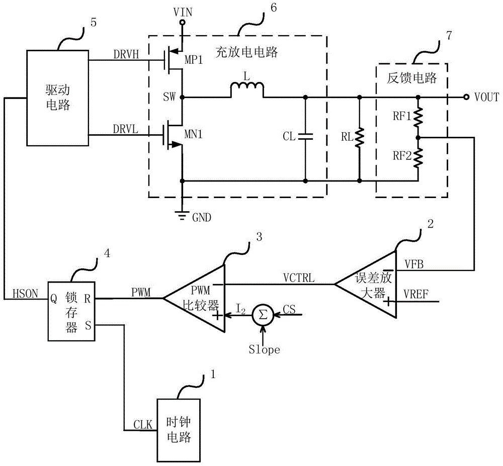
[0054] figure 1 shows a block diagram of a prior art synchronous step-down DC-DC converter, such as figure 1 As shown, prior art synchronous step-down DC-DC converters include:

[0055] A clock circuit 1, the output terminal of the clock circuit 1 is connected to the setting terminal S of the latch 4;

[0056] Error amplifier 2, the positive phase input terminal of the error amplifier 2 inputs the reference voltage signal VREF, the negative phase input terminal of the error amplifier 2 is connected to the output terminal of the feedback circuit, and the output terminal of the error amplifier 2 is connected to the negative phase input terminal of the PWM comparator ;

...


PUM


Abstract

The invention provides a synchronous buck DC-DC converter capable of achieving low output ripples in times of underloading. A frequency-down circuit is additionally arranged on the structural basis of the synchronous buck DC-DC converter, and accordingly the problem of being large in output ripple in times of underloading is mainly solved. The frequency-down circuit comprises a transconductance amplifier and a clock circuit. The transconductance amplifier is used for detecting whether the output end of the DC-DC converter is underloaded or not, the clock circuit lowers the frequency of clock signals CLK in times of underloading, and the output ripples in times of underloading are greatly reduced while a feedback circuit has enough time to adjust input power so as to be adapted to change of output loads and to improve underloading efficiency of the converter. The application range of the converter is widened, and the performance of the converter is improved.

Description

technical field [0001] The invention relates to the field of electronic technology, in particular to a synchronous step-down DC-DC converter with low output ripple at light load. Background technique [0002] In the field of power management, the output ripple of the synchronous step-down DC-DC converter is a very important indicator. To make the output ripple the lowest, it is necessary to ensure that the input power matches the load power consumption, so that the converter is in a stable working state . [0003] In the typical topology of a synchronous step-down DC-DC converter, the method of increasing the output capacitor is usually used to solve the problem of excessive output ripple, but the increase of the output filter capacitor increases the time constant, which leads to the converter The delay of the loop increases, so that the operating frequency and application range of the converter are limited. [0004] In the prior art, when the converter works at light load...

Claims


Application Information

Patent Timeline
Patent Type & Authority Applications(China)
IPC IPC(8): H02M3/156H02M1/14
Inventor 席小玉惠惠
Owner XI AN M3 SEMICONDUCTOR INC
Why Eureka
Try Eureka