LLC resonance power converter with double resonance frequencies

A technology of power converter and dual resonant frequency, which is applied in the direction of output power conversion device, conversion of DC power input to DC power output, and adjustment of electric variables, etc., which can solve the problems of large power loss and deviation of magnetic flux density, and achieve cost reduction. Low cost, simple circuit, good reliability

Active Publication Date: 2016-10-26
SOUTHEAST UNIV
View PDF3 Cites 15 Cited by
  • Summary
  • Abstract
  • Description
  • Claims
  • Application Information

AI Technical Summary

Problems solved by technology

However, these schemes use complex auxiliary windings or asymmetric pulse width modulation (APWM)

Method used


Image

  • LLC resonance power converter with double resonance frequencies
  • LLC resonance power converter with double resonance frequencies
  • LLC resonance power converter with double resonance frequencies

Examples


Example Embodiment

[0034] The technical solution of the invention will be described in detail below in conjunction with the accompanying drawings.

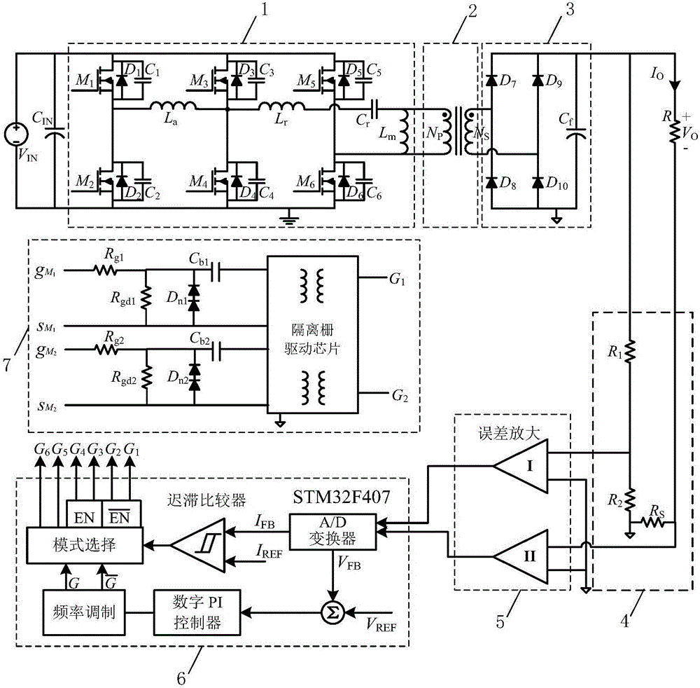
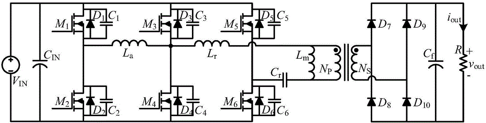
[0035] like figure 1 As shown, the resonant network of the traditional LLC resonant power converter is equipped with four NMOS transistors M 3 , M 4 , M 5 and M 6 , inductance Lr and Lm and capacitance Cr, NMOS tube M 3 and M 4 Constitute a bridge arm, NMOS tube M 5 and M 6 Constitute another bridge arm, NMOS tube M 3 The source is connected to the NMOS transistor M 4 The drain and one end of the inductor Lr, the NMOS tube M 5 The source is connected to the NMOS transistor M 6 The drain and one end of the inductance Lm, the other end of the inductance Lm is connected in series with the capacitor Cr and then connected to the other end of the inductance Lr, the NMOS transistor M 3 and M 5 The drains are connected to the input voltage V IN Positive terminal, NMOS tube M 4 and M 6 The sources are connected to the input voltage V IN The n...


PUM


Abstract

The invention discloses an LLC resonance power converter with double resonance frequencies. On the basis of the traditional LLC resonance power converter resonance network formed by two bridge arms and four NMOS transistors M3, M4, M5 and M6, a bridge arm formed by NMOS transistors M1 and M2 is additionally arranged, an active network is formed together with an inductor La, an isolation transformer and a Class D full bridge rectifier are serially connected sequentially, the Class D full bridge rectifier is sequentially connected with a sampling circuit, an error amplification circuit, an STM32F407 microcontroller and a high-frequency gate driving circuit via a load R, and output of the high-frequency gate driving circuit drives three bridge arms and six MOS transistors from M1 to M6 in the resonance network additionally provided with the active network to work normally. The LLC resonance power converter with double resonance frequencies has two working modes, the light-load efficiency of the LLC resonance converter is greatly improved, a switching frequency range is narrow, and symmetric work in a full load range is realized.

Description

technical field [0001] The invention relates to a DC / DC power converter, in particular to an LLC resonant power converter with double resonance frequencies. Background technique [0002] At present, for modern switching power supplies used in commercial DC power supplies and industrial power supply units, there are requirements for high efficiency, high power density, small size, and high reliability. The power supply usually consists of a two-stage structure, the first stage is a step-up power factor correction stage, and the second stage is a high-frequency link DC / DC conversion stage. The full bridge structure is widely used in the second stage due to its low voltage stress and smaller transformer size. [0003] Due to the relatively large loss and oscillation of the switching device in the traditional full-bridge structure, it is gradually replaced by the zero-voltage switching (ZVS) full-bridge structure, and the phase-shifted full-bridge (PSFB) structure realizes the ...

Claims


Application Information

Patent Timeline
IPC IPC(8): H02M3/335
CPCH02M3/33523H02M3/3353H02M3/33569Y02B70/10
Inventor 孙伟锋田豪傑俞居正苏畅钱钦松陆生礼时龙兴
Owner SOUTHEAST UNIV
Why Eureka
Try Eureka