Adaptive drive method for synchronous rectification of flyback converter

A flyback converter, synchronous rectification technology, applied in the direction of converting DC power input to DC power output, instruments, adjusting electrical variables, etc. Easy to stabilize, reduce light load loss and improve efficiency

Inactive Publication Date: 2014-03-26
SOUTH CHINA UNIV OF TECH
View PDF3 Cites 15 Cited by
  • Summary
  • Abstract
  • Description
  • Claims
  • Application Information

AI Technical Summary

Problems solved by technology

This method is applicable to light-load and heavy-load working modes, but at light load, if the turn-on time of the secondary side drive is still maintained at 1-D, the turn-on time will be too long, which will cause current backflow in the secondary side, making the no-load The loss is large, and the loop is not easy to stabilize
like figure 2 As shown, the flyback converter synchronous rectification drive signal generation method based on secondary current detection is used. When using no-load and light load, the secondary circuit works in the current discontinuous mode (DCM). By detecting the current zero-crossing point, Realize the turn-on and turn-off of the secondary side synchronous rectification drive signal, thereby effectively avoiding the problem of large loss at light load, but in the heavy-load working environment, the secondary side circuit works in the continuous current mode (CCM), and there is no current zero-crossing point. ZCD (current zero-crossing detection) fails, and the synchronous rectifier tube cannot be turned off, which may cause common problems and cause circuit damage

Method used


Image

  • Adaptive drive method for synchronous rectification of flyback converter
  • Adaptive drive method for synchronous rectification of flyback converter
  • Adaptive drive method for synchronous rectification of flyback converter

Examples


Embodiment

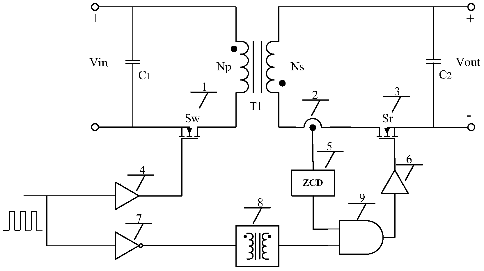
[0029] Such as image 3 Shown is the circuit composition diagram for realizing the method of the present invention, in order to realize the self-adaptive regulation of the load variation of the synchronous rectifier drive signal of the secondary side, the circuit composition diagram for realizing the method of the present invention includes the main circuit flyback converter Using synchronous rectification topology, primary side drive tube 1, secondary side rectification drive tube 3, secondary side current detection circuit 2, current zero-crossing detection (ZCD) 5, AND gate logic circuit 9, isolation circuit 8, drive circuits 4 and 6 and reverse circuit 7.

[0030] Set the duty ratio of the PWM signal driven by the primary side to D, and obtain the PWM signal through the reverse circuit 7 with a duty ratio of 1-D.

[0031] When the flyback converter works under heavy load conditions and the circuit works in the current continuous mode, the primary and secondary currents ha...


PUM


Abstract

The invention discloses an adaptive drive method for synchronous rectification of a flyback converter. The method includes the steps of 1, composing a secondary side current detection circuit, a current zero-cross detection circuit, an AND gate logic circuit, an isolating circuit, a drive circuit and a reverse circuit into a secondary side drive circuit; 2, determining a drive signal of a secondary side synchronous rectifier tube according to the output of the AND gate logic circuit; 3, using input of the AND gate logic circuit as an output value of a primary side PWM drive reverse signal and circuit zero-cross detection circuit. The method is applied to implementation of adaptive drive signals of synchronous rectifier tubes for the flyback converter using synchronous rectification and has the advantages that the method can effectively adapt to defects such as low efficiency, high no-load loss and difficulty in loop stabilization during light loading, and efficient, stable operation of the circuit is achieved.

Description

technical field [0001] The invention relates to an adaptive realization method for synchronous rectification tube drive signal generation when a flyback converter adopts a synchronous rectification mode, in particular to an adaptive driving method for a flyback converter synchronous rectification. Background technique [0002] Synchronous rectification technology is one of the main key technologies applied to low-voltage and high-current DC / DC rectification in the field of switching power supplies. Combined with an appropriate circuit topology, a low-cost, high-efficiency converter can be realized. Among them, the flyback converter formed by the flyback circuit topology is most widely used in low-power occasions because of its simplicity, reliable operation, and easy design and production. For the flyback converter, when the synchronous rectification technology is used, how to realize the driving signal management of the secondary side synchronous rectification drive tube b...

Claims


Application Information

Patent Timeline
Patent Type & Authority Applications(China)
IPC IPC(8): H02M3/335H02M1/38
CPCY02B70/1475Y02B70/10
Inventor 冯顺萍梁土福冯颖苏春翌
Owner SOUTH CHINA UNIV OF TECH
Why Eureka
Try Eureka