Working size switching circuit for power transistors in DC-DC converter

A technology of DC-DC and switching circuits, applied in the direction of DC power input conversion to DC power output, output power conversion devices, instruments, etc., can solve the problems of low efficiency, large charge and discharge loss, etc., to improve consistency, reduce Small power consumption, the effect of improving light load efficiency

Active Publication Date: 2012-07-11
深圳德信微电子有限公司
View PDF1 Cites 16 Cited by
  • Summary
  • Abstract
  • Description
  • Claims
  • Application Information

AI Technical Summary

Problems solved by technology

For large-sized power tubes, the huge parasitic capacitance of the gate leads to large charge and discharge losses, so the efficiency is very low at light loads

Method used


Image

  • Working size switching circuit for power transistors in DC-DC converter
  • Working size switching circuit for power transistors in DC-DC converter
  • Working size switching circuit for power transistors in DC-DC converter

Examples


Embodiment Construction

[0019] The present invention will be further described below in conjunction with accompanying drawings and embodiments thereof.

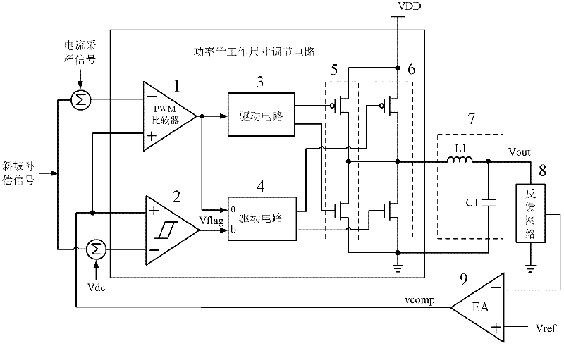
[0020] refer to figure 2 , the current mode DC-DC converter using the power tube working size switching circuit of the present invention includes: a power tube size adjusting circuit, an output LC filter 7, a feedback network 8, an error amplification module 9, a slope compensation signal and a current sampling signal. The slope compensation signal and the current sampling signal are respectively generated by the oscillation module and the current sampling module inside the chip, and these two modules are not shown in the figure.

[0021] The power tube working size switching circuit of the present invention includes: a pulse width modulation PWM comparison module 1, a first drive module 3, a first pair of power MOS tubes 5, a hysteresis comparison module 2, a second drive module 4 and a second pair of power MOS tubes 6. The output terminal of th...


PUM


Abstract

The invention discloses a working size switching circuit for power transistors in a DC-DC converter, mainly solving the problem of difficulty in reaching high efficiency by the traditional DC-DC converter when in a low load state. The working size switching circuit comprises a pulse width modulation (PWM) comparing module, a first drive module, a first pair of power MOS (Metal Oxide Semiconductor) transistors, a hysteresis comparing module, a second drive module and a second pair of power MOS transistors, wherein the PWM comparing module controls the first pair of power MOS transistors to work through the first drive module; the hysteresis comparing module compares a load current with a switching threshold current to generate a judging signal and controls that the second pair of power MOS transistors does not work when the load current is lower than the switching threshold current through the second drive module and the second pair of power MOS transistors works when the load current is more than the switching threshold current, so that actually working power transistors of the DC-DC converter are different in quantity under same load conditions, and the working size of the power transistors are switched. According to the working size switching circuit, the efficiency of the DC-DC converter when in the light load state can be increased, and load currents corresponding to the switching of the working sizes of the power transistors are constant under various working duty ratios.

Description

technical field [0001] The invention belongs to a DC-DC converter in a large-scale analog integrated circuit, in particular to a power tube size adjustment circuit in the converter, which can be used in a DC-DC converter. Background technique [0002] As an important power management circuit, DC-DC converters are widely used in various portable products such as mobile phones, MP3 players, and digital cameras. According to the relationship between output and input voltage, DC-DC converters can usually be divided into three categories: step-up DC-DC converters, step-down DC-DC converters, and step-down DC-DC converters. Each type of DC-DC is divided into current mode control DC-DC and voltage mode control DC-DC according to the chip control loop. Compared with linear regulators, switching power management chips, such as DC-DC converters, have the biggest advantage of high efficiency. Therefore, in recent years, low power consumption and high efficiency designs have become pop...

Claims


Application Information

Patent Timeline
Patent Type & Authority Applications(China)
IPC IPC(8): H02M3/00H02M1/08H02M3/155
Inventor 来新泉袁冰刘洁何全涛赵竞翔
Owner 深圳德信微电子有限公司
Why Eureka
Try Eureka