Pump unit

a technology of pump unit and axial installation length, which is applied in the direction of machines/engines, liquid fuel engines, positive displacement liquid engines, etc., can solve the problem of comparatively large axial installation length of pump units, and achieve the effect of convenient rotation, robust and cost-effective, and better starting

Inactive Publication Date: 2016-04-07
ROBERT BOSCH GMBH
View PDF11 Cites 2 Cited by
  • Summary
  • Abstract
  • Description
  • Claims
  • Application Information

AI Technical Summary

Benefits of technology

[0005]It is advantageous if the magnets on the drive shaft are located off-center with respect to the stator and as viewed in the direction of the drive axis, such that the drive shaft is pressed with a predetermined magnetic force against the rotor. This results from the fact that the drive shaft and the rotor are continually pressed with a constant magnetic force against the teeth of the housing. As a result, the pump unit can be better started when switching on the electric motor. Stated in other words, the drive shaft and the rotor can be more easily set into rotation.
[0006]It is furthermore advantageous if the magnets are permanent magnets because a permanently excited electric machine is formed.
[0007]According to an advantageous embodiment of the invention, the drive shaft is encased by a cylinder in the region of the magnets because the magnets are encapsulated and protected from the fluid of the pump unit in this way.
[0008]It is very advantageous if a shaft bearing is provided for mounting the drive shaft at each end face of the stator because the drive shaft is precisely mounted in this manner.
[0009]It is also advantageous, if the shaft bearing is designed as a slide bearing, because slide bearings can be implemented in a particularly robust and cost-effective manner.
[0010]In addition, it is advantageous if the shaft bearings are provided on a disk-shaped or annular component. It is additionally advantageous if the shaft bearings are injection molded with a plastic material to the stator because the shaft bearings can be implemented in this way particularly cost effectively and the function of the shaft bearing is integrated into the plastic of the molding.

Problems solved by technology

It is disadvantageous that the pump unit has a comparatively large axial installation length, because the drive of the pump is arranged on an end of the drive shaft facing away from the rotor.

Method used


Image

  • Pump unit
  • Pump unit

Examples


Embodiment Construction

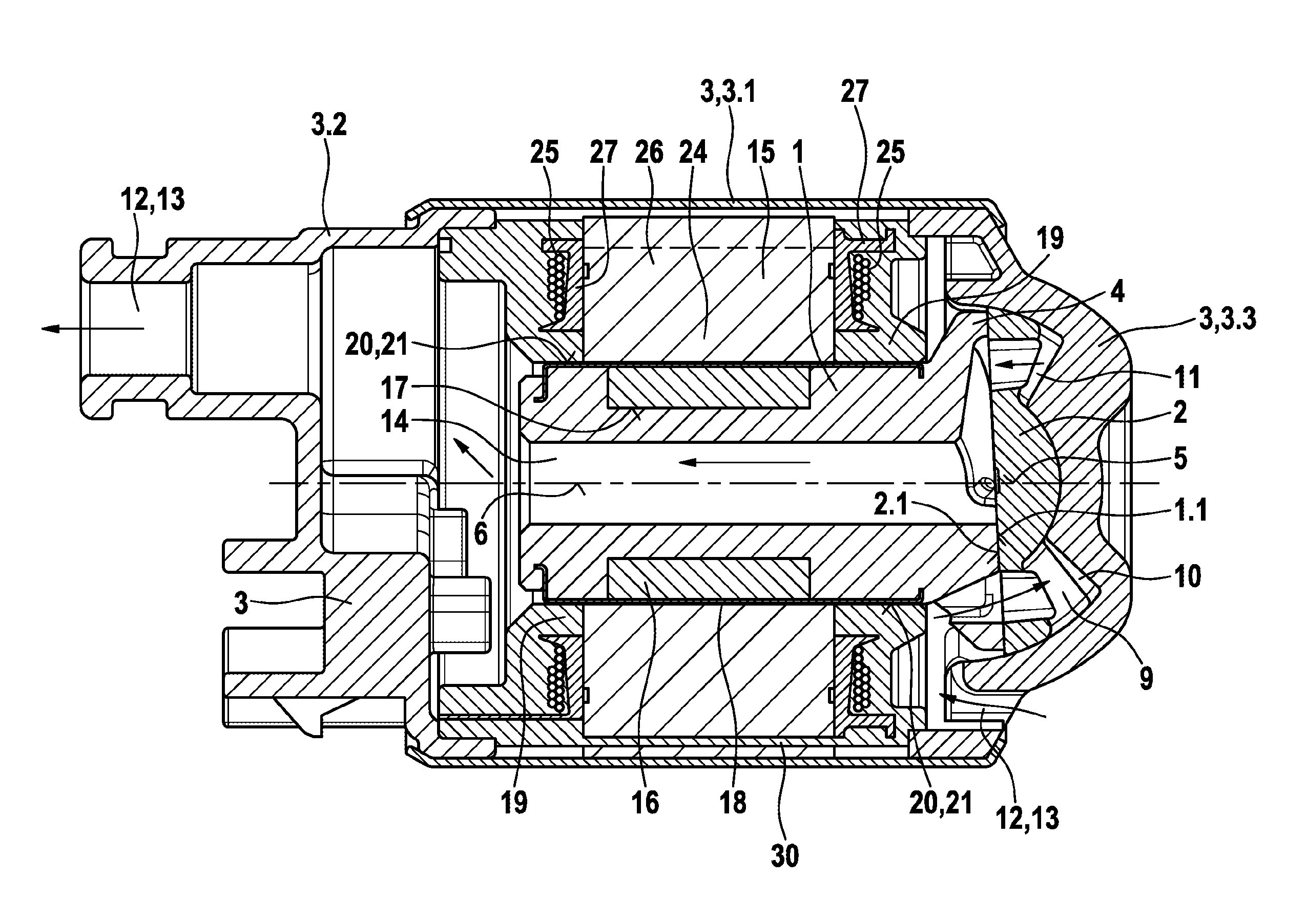
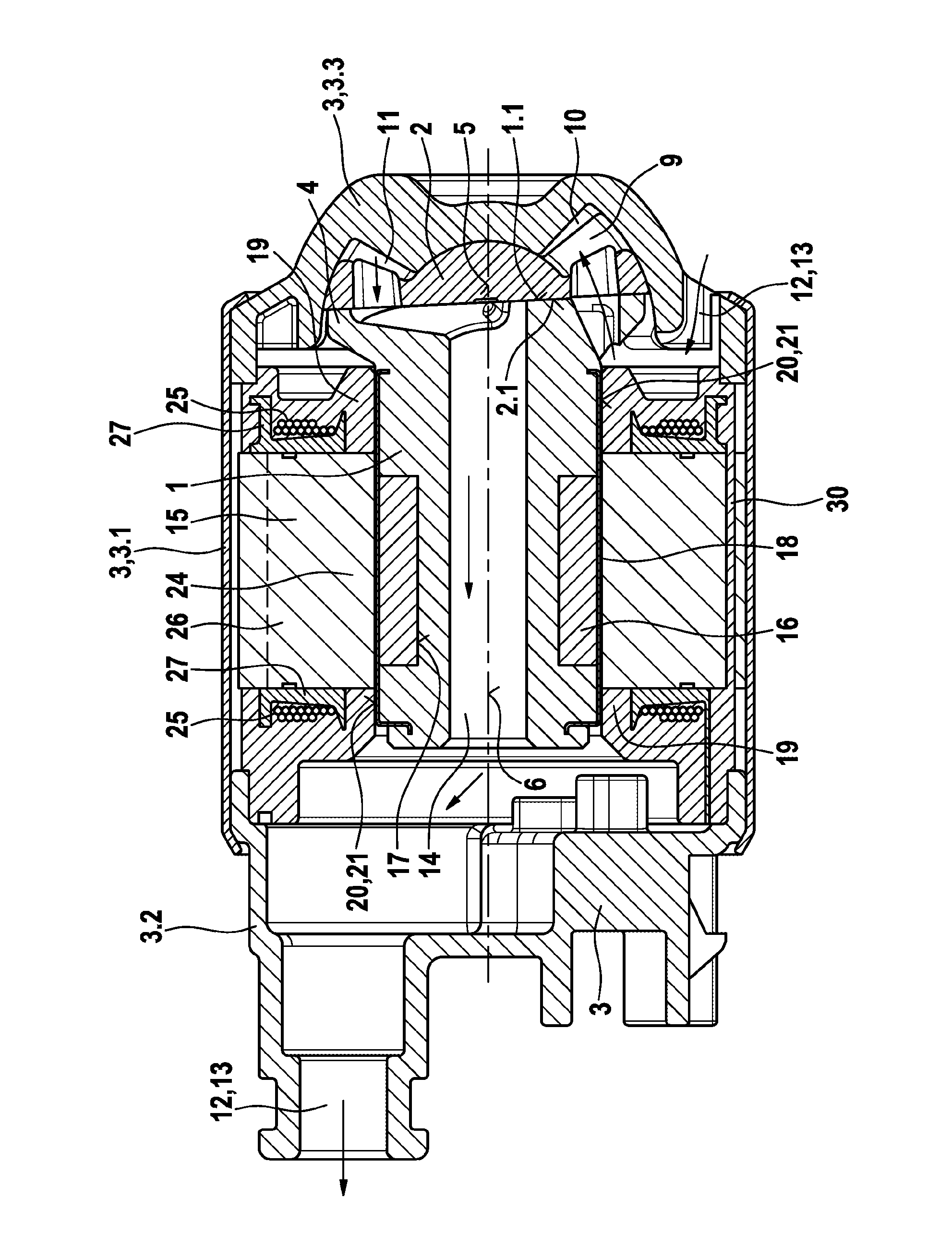
[0013]The pump unit, for example a pump or a compressor, comprises a drive shaft 1, which drives a rotor 2 that is arranged rotatably in a housing 3. The drive shaft 1 has an oblique sliding plane 1.1 on the end thereof facing the rotor 2, said sliding plane interacting with the rotor 2. The sliding plane 1.1 is, for example, formed on a shoulder 4 of the drive shaft 1 and allows the rotor 2 to nutate with the rotor axis 5 thereof about a drive axis 6 of the drive shaft 1. The rotor 2 has a sliding surface 2.1 which interacts with the oblique sliding plane 1.1 on the side thereof facing the drive shaft 1 and a set of teeth 9 on the end face thereof facing away from the drive shaft 1, said teeth meshing with the set of teeth 10 formed on the housing 3. Working spaces 11 are formed between the teeth 9 of the rotor 2 and the teeth 10 of the housing 3, which working spaces can be filled via an inlet 12 of the pump unit and emptied via an outlet 13 of the pump unit. The teeth 9 of the ro...


PUM


Abstract

Pump units are known that have a drive shaft and a rotor, which is driven by the drive shaft and is arranged rotatably in a housing, the drive shaft having an oblique sliding plane, which interacts with the rotor and allows the rotor to nutate with the rotor axis thereof about a drive axis of the drive shaft, the rotor having a set of teeth on the end face of the rotor facing away from the drive shaft, said teeth meshing with a set of teeth formed on a housing of the pump unit, working spaces being formed between the teeth of the rotor and the teeth of the housing, which working spaces can be filled via an inlet and emptied via an outlet. It is disadvantageous that the pump unit has a comparatively large axial installation length, because the drive of the pump unit is arranged on an end of the drive shaft facing away from the rotor. In the pump unit according to the invention, the axial installation length is shortened. According to the invention the drive shaft (1) is surrounded by a stator (15) and magnets (16) are provided on the drive shaft (1), which magnets interact magnetically with the stator (15).

Description

BACKGROUND OF THE INVENTION[0001]The invention relates to a pump unit.[0002]A pump unit is already known from the German patent publication DE 10 2010 040 758 A1, comprising a drive shaft and a rotor, which is driven by the drive shaft and is arranged rotatably in a housing, the drive shaft having an oblique sliding plane, which interacts with the rotor and allows the rotor to nutate with the rotor axis thereof about a drive axis of the drive shaft, the rotor having a set of teeth on the end face of the rotor facing away from the drive shaft, said teeth meshing with a set of teeth formed on a housing of the pump unit, working spaces being formed between the teeth of the rotor and the teeth of the housing, which working spaces can be filled via an inlet and emptied via an outlet. It is disadvantageous that the pump unit has a comparatively large axial installation length, because the drive of the pump is arranged on an end of the drive shaft facing away from the rotor.SUMMARY OF THE ...

Claims


Application Information

Patent Timeline
Patent Type & Authority Applications(United States)
IPC IPC(8): F04C15/00F04C3/08
CPCF04C3/08F04C15/008F04C11/008F04C2240/60H02K1/278H02K5/128H02K7/088
Inventor NOWITZKY, INGOAMESOEDER, DIETERLAFORSCH, OLIVERKUNATH, SANDOSKRYNSKI, EVGENIJKACMAR, MARIAN
Owner ROBERT BOSCH GMBH
Why Eureka
Try Eureka