Vertical take off and landing aircraft

a vertical take-off and landing technology, applied in the field of aircraft, can solve the problems of limiting commuters to roads, cruising speed, and inability to pivot the propeller for horizontal fligh

Inactive Publication Date: 2016-04-14
TOPPENBERG DAVID WAYNE
View PDF0 Cites 27 Cited by
  • Summary
  • Abstract
  • Description
  • Claims
  • Application Information

AI Technical Summary

Problems solved by technology

Current automobile technology limits commuters to roads which are increasingly congested.
Helicopters and gyro copters, while enabling vertical takeoff, cannot pivot their propellers for horizontal flight.
This limits their cruising speed typically to <200 knots which reduce

Method used


Image

  • Vertical take off and landing aircraft
  • Vertical take off and landing aircraft
  • Vertical take off and landing aircraft

Examples


Embodiment Construction

[0017]The following detailed description is of the best currently contemplated modes of carrying out exemplary embodiments of the invention. The description is not to be taken in a limiting sense, but is made merely for the purpose of illustrating the general principles of the invention, since the scope of the invention is best defined by the appended claims.

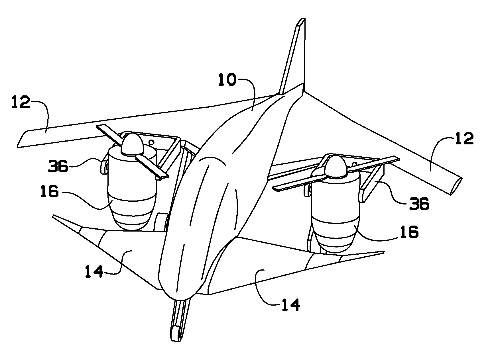
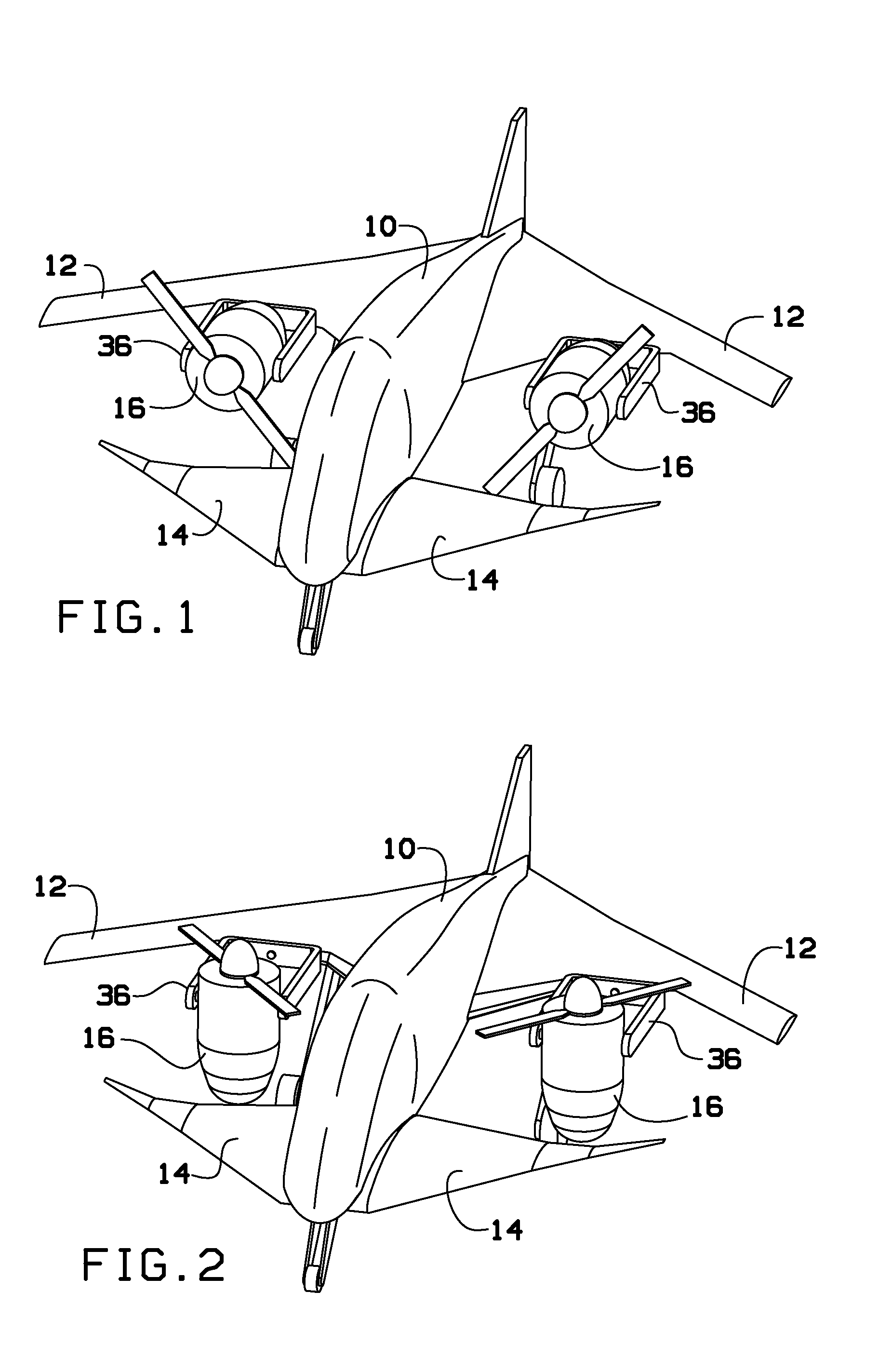
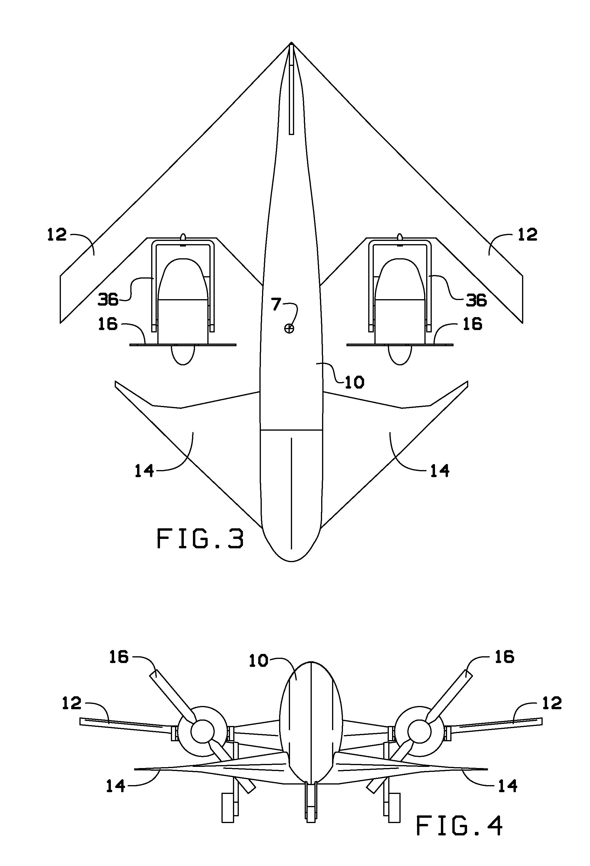
[0018]Broadly, the present invention includes a vertical takeoff and landing aircraft. The aircraft includes a fuselage having a first end, a second end, and a center of gravity in between the first end and the second end. Wings may extend from the side of the fuselage. The wings may include a canard at the first end, and a forward swept wing at the second end. The present invention may further include a pair of engines pivotally attached on either side of the fuselage and substantially aligning with the center of gravity.

[0019]The present invention includes a vertical takeoff and landing aircraft that can be parked in a two car...


PUM


Abstract

A vertical takeoff and landing aircraft is provided. The aircraft includes a fuselage having a first end, a second end, and a center of gravity in between the first end and the second end. Wings may extend from the side of the fuselage. The wings may include a canard at the first end, and a wing at the second end. The present invention may further include a pair of engines pivotally attached on either side of the fuselage and substantially aligning with the center of gravity.

Description

BACKGROUND OF THE INVENTION[0001]The present invention relates to an aircraft and, more particularly, to a vertical takeoff and landing aircraft.[0002]Commuters need fast door to door transportation to get to and from work, particularly in urban areas. Current automobile technology limits commuters to roads which are increasingly congested. Lengthy commute times result which limits the growth of current urban centers. Current conventional takeoff and landing aircraft require runways which prevent them from providing practical door to door transportation.[0003]Helicopters and gyro copters, while enabling vertical takeoff, cannot pivot their propellers for horizontal flight. This limits their cruising speed typically to <200 knots which reduces their utility in shortening commutes in ever enlarging urban areas. Existing straight wing pivoting propeller aircraft designs do not directly scale down to fit into a typical two car garage or enable them to economically carry two to five p...

Claims


Application Information

Patent Timeline
IPC IPC(8): B64C29/00
CPCB64C29/0033B64C39/12
Inventor TOPPENBERG, DAVID WAYNE
Owner TOPPENBERG DAVID WAYNE
Why Eureka
Try Eureka