Cap for a container

a container and cap technology, applied in the field of caps, can solve the problems of product entry or settling in the peripheral groove between the sealing skirt and the inner peripheral wall, the peripheral groove cannot be filled, and the product loses the flexibility required, so as to achieve the effect of improving storage performan

Active Publication Date: 2016-04-14
AIRNOV INC
View PDF7 Cites 15 Cited by
  • Summary
  • Abstract
  • Description
  • Claims
  • Application Information

AI Technical Summary

Benefits of technology

[0008]It is an object of the present invention to provide a cap for a container which avoids the above mentioned problems, thereby providing a cap with improved storage performance.

Problems solved by technology

As products accommodated in the container may be of small size or flat-shaped, there is a risk that the products enter or get stuck in the peripheral groove between the sealing skirt and the inner peripheral wall.
However, to avoid this problem, the peripheral groove cannot be filled for providing a connection between the sealing skirt and the inner peripheral wall, because the sealing skirt would in this case lose its flexibility required for providing an air-tight connection to the tubular container.
However, these caps have several disadvantages.
Firstly, the height of the desiccant chamber must be smaller than the height of the sealing skirt and cannot be adjusted or increased according to the volume of the required desiccant.
Secondly, when fitted in an inner wall of the container, the deformation of the sealing skirt providing the airtightness can lead to a deformation of the cardboard, which again may move, fold, corrugate or loosen from the inner peripheral wall.
In this case, the desiccant leaks from the desiccant chamber.

Method used


Image

  • Cap for a container
  • Cap for a container
  • Cap for a container

Examples


Embodiment Construction

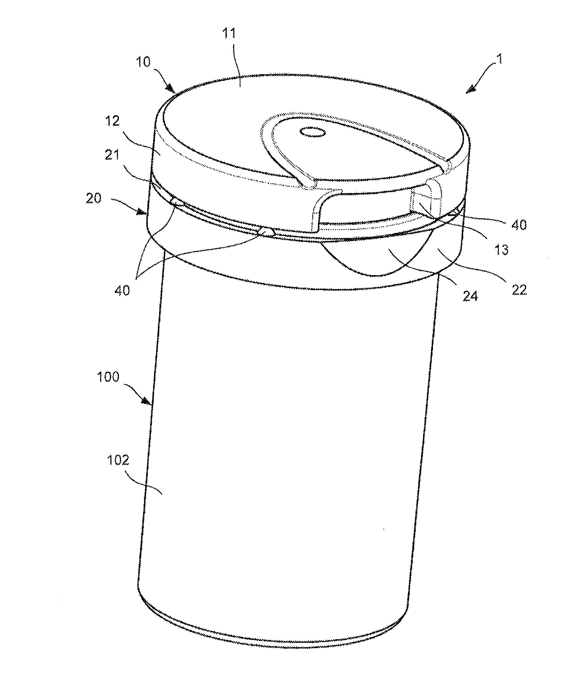
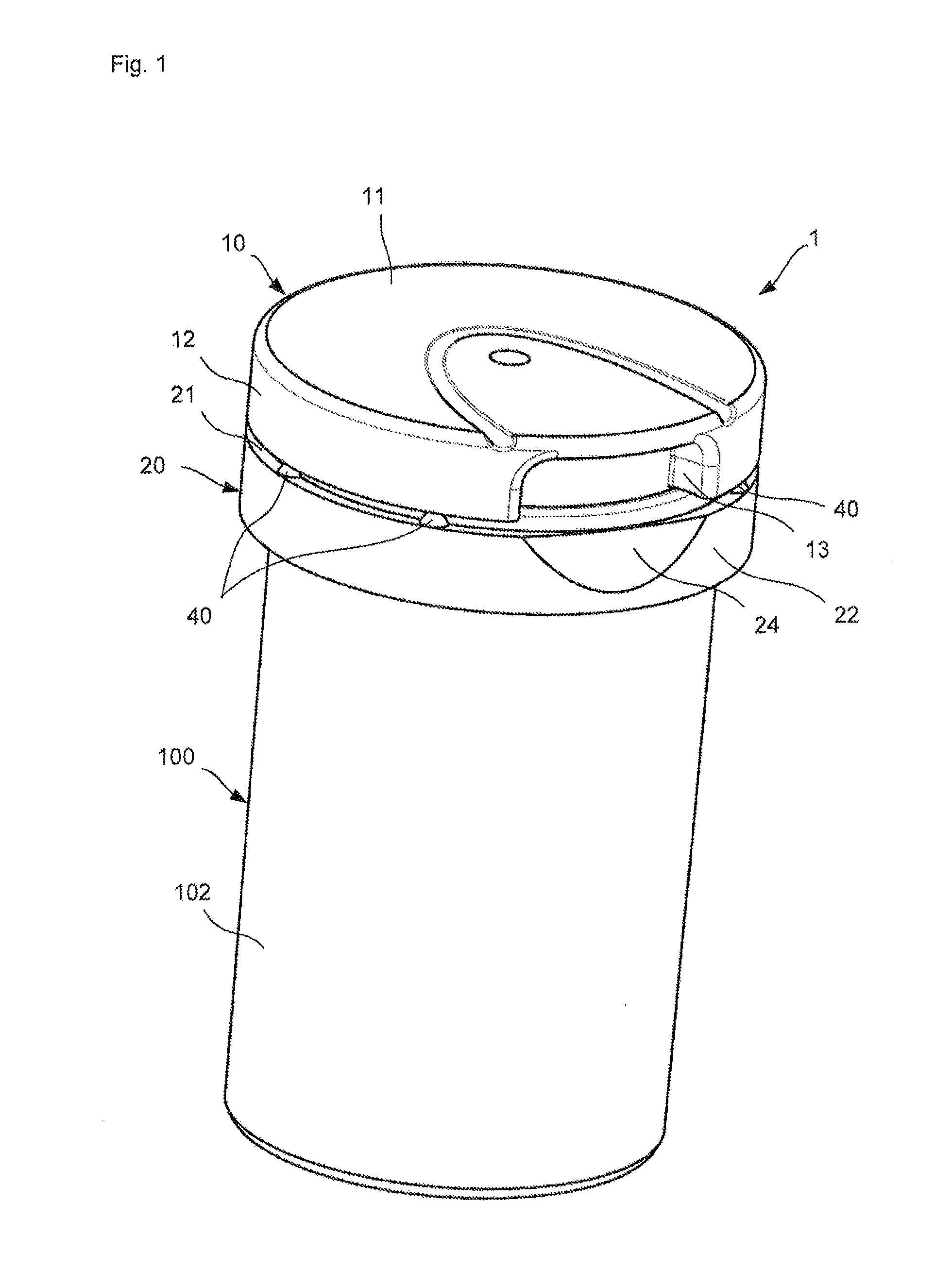
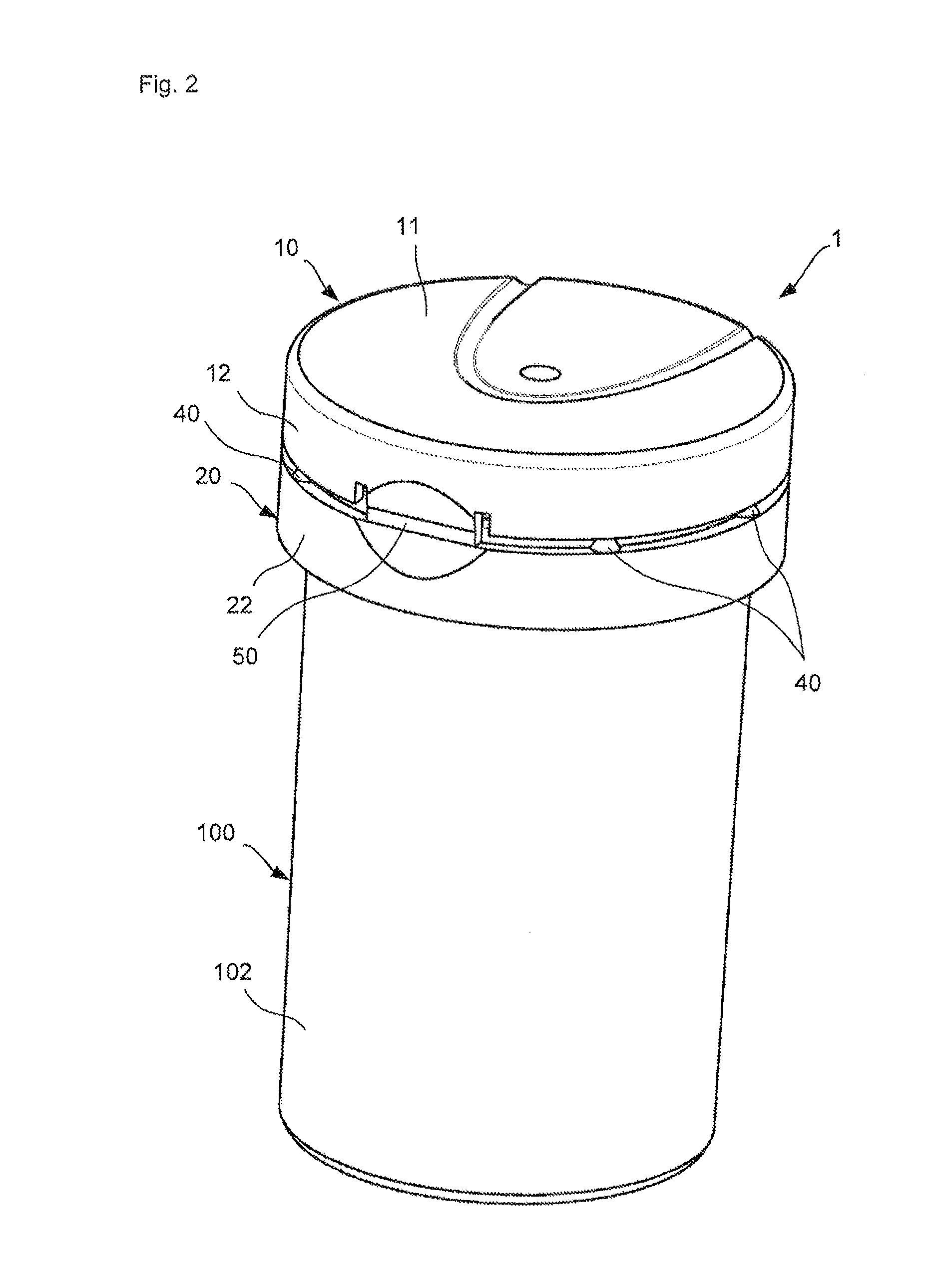
[0041]The following explanations refer to a preferred embodiment of a cap for a container according to the present invention, which is described with reference to FIGS. 1-10. Further modifications and variations of single features mentioned in connection with the present embodiment may each be combined with each other, respectively, thereby providing additional embodiments of the present invention.

[0042]A cap 1 according to the present embodiment is attached to a tubular container 100, wherein the container 100 has a substantially cylindrical form with a closed bottom portion 101, a peripheral wall portion 102 and an opening 103 opposite to the bottom portion 101. A rib portion 104 is formed adjacent to the opening 103 on the peripheral wall portion 102. The rib portion 104 can interact with a corresponding part of the cap 1.

[0043]The cap 1 comprises a lid body 10 and a ring-element 20, which are connected to each other by a film hinge 50 and a plurality of frangible webs 40 arrange...


PUM


Abstract

Disclosed is a cap for a container and a container comprising such cap. This container typically accommodates loosely stored, solid products, such as strips, pills, tablets or the like. The cap includes a lid body with a top part and a peripheral wall, wherein the lid body includes a sealing skirt and an inner peripheral wall, which extend from the top part, and form a peripheral groove in between. At least one projection portion for partially covering the peripheral groove is integrally formed with the sealing skirt and the inner peripheral wall.

Description

TECHNICAL FIELD[0001]The present invention refers to a cap for a container, and a container comprising such a cap. Such preferably substantially tubular or cylindrical containers typically accommodate loosely stored, solid products, such as strips, pills, tablets or the like. The cap is attached to the container for closing the opening thereof so that the products contained therein are protected during storage.STATE OF THE ART[0002]Caps for containers in the above-mentioned field are typically manufactured separately from the container. The caps are then connected to the container once the container is filled with products to be contained therein.[0003]A tamper-evident closure for tablet tubes is, for example, known from WO 2007 / 057133 A1. The closure / cap comprises a ring connected to the container and a lid, which again is connected to the ring by means of a hinge and tear-off / tamper-evident webs between the ring and the lid.[0004]Caps of this type generally have a sealing skirt fo...

Claims


Application Information

Patent Timeline
Patent Type & Authority Applications(United States)
IPC IPC(8): B65D53/02B65D51/24
CPCB65D53/02B65D2101/0076B65D51/24B65D47/0838B65D51/244B65D2401/20B65D2401/50
Inventor LOGEL, VALERELEBON, JACQUYPOT, CAROLINE
Owner AIRNOV INC
Why Eureka
Try Eureka