System for and method of estimating bearings of radio frequency identification (RFID) tags that return RFID receive signals whose power is below a predetermined threshold

Active Publication Date: 2016-04-14
SYMBOL TECH LLC
View PDF13 Cites 22 Cited by
  • Summary
  • Abstract
  • Description
  • Claims
  • Application Information

AI Technical Summary

Benefits of technology

The present patent is about a system and method for accurately estimating the bearings of RFID tags in a controlled area, especially in a real-world environment where the receive signals may have low power. The system uses multiple antenna elements and a search pattern to capture the return RFID signals and process them to generate accurate bearing information. However, there are times when real-world conditions may interfere with the generation and processing of the signals, resulting in errors in the bearing estimation. The patent proposes a solution to improve the accuracy of estimating the true bearing of a tag in such a real-world environment.

Problems solved by technology

However, there is a practical limit on the number of antenna elements that can be used in each array.
However, estimating the bearing, i.e., the angular direction both in azimuth and elevation, of any particular tag based on the peak RSSI of the return primary receive signal is imprecise due to the aforementioned relatively broad beam width.
Bearing errors on the order of 5 to 10 degrees have been reported and are not readily tolerable in locationing applications.
For example, the controlled area may contain shelving, fixtures, equipment, vehicles, and the like, not to mention the floor, the ceiling and the room walls, each or all of which can reflect and scatter the primary and / or secondary receive beams incident thereon, thereby compromising the generation and processing of their corresponding receive signals such that one or more of such receive signals have no or low power, i.e., their RSSI is below a minimum acceptable threshold, due to multi-path reflections, destructive interference among signals, ambient temperature variations, etc.
As a result, the known RFID system cannot always accurately estimate the true bearing of a tag for such a real-world environment.

Method used


Image

  • System for and method of estimating bearings of radio frequency identification (RFID) tags that return RFID receive signals whose power is below a predetermined threshold
  • System for and method of estimating bearings of radio frequency identification (RFID) tags that return RFID receive signals whose power is below a predetermined threshold
  • System for and method of estimating bearings of radio frequency identification (RFID) tags that return RFID receive signals whose power is below a predetermined threshold

Examples


Embodiment Construction

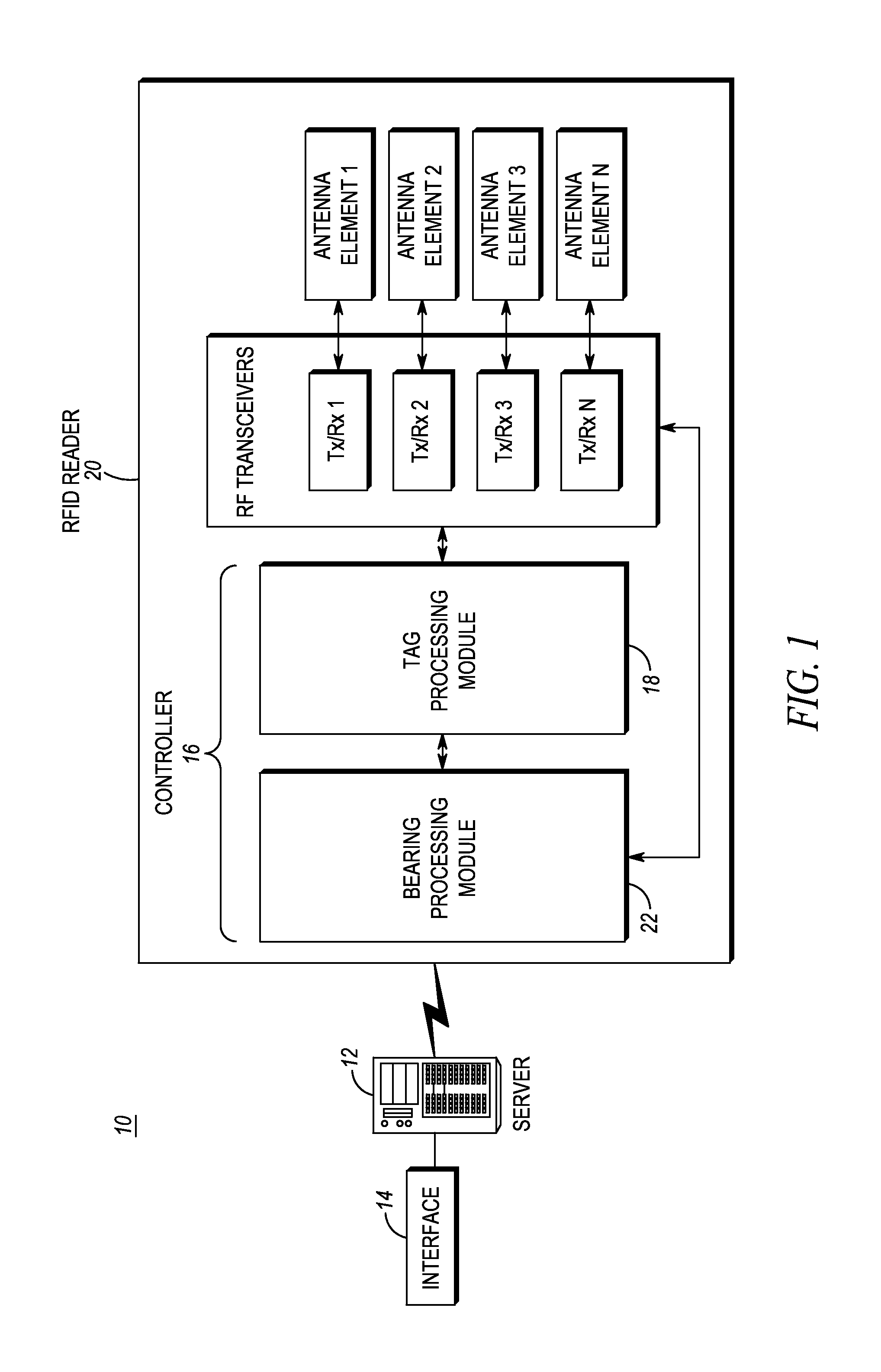
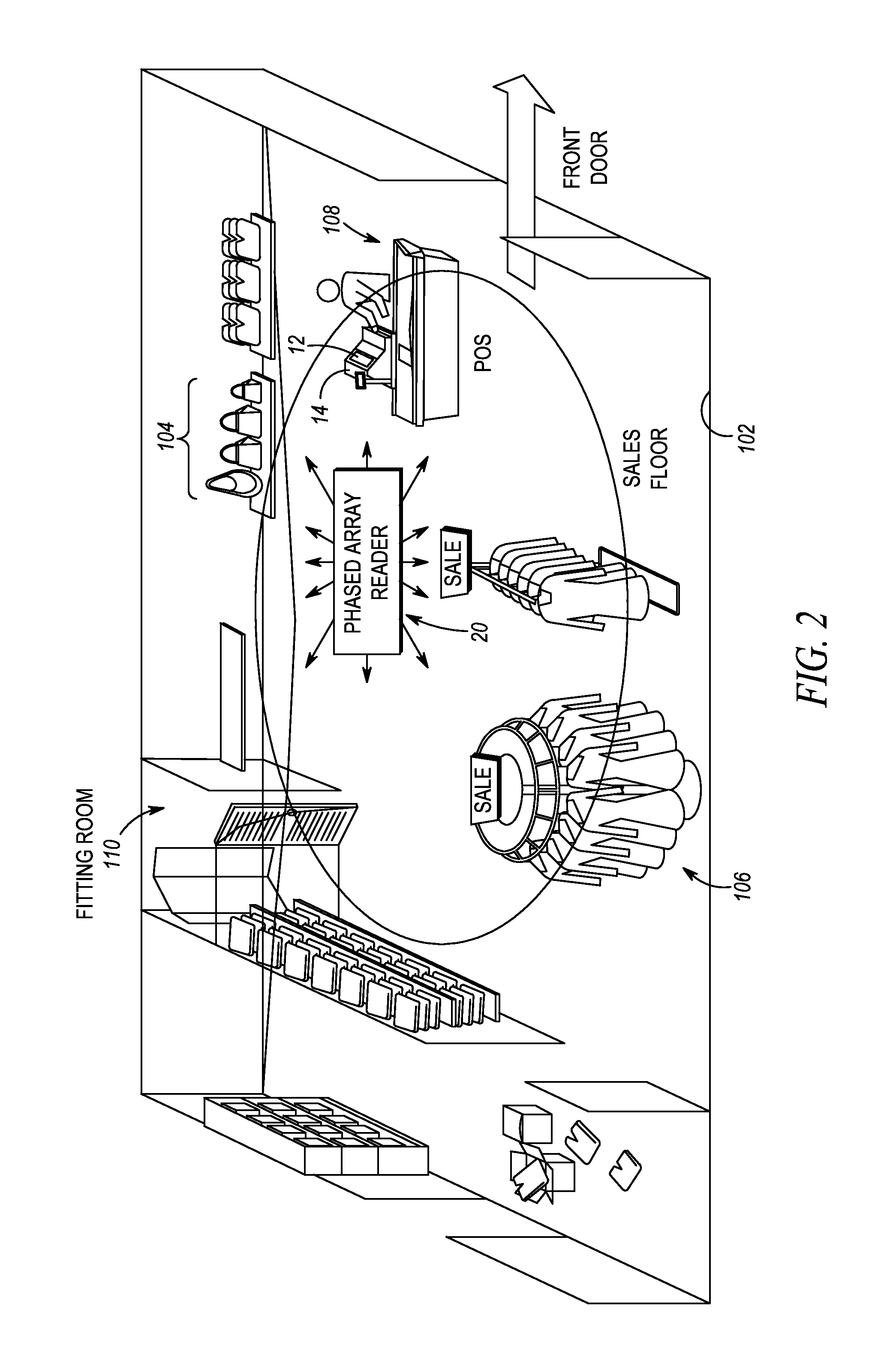
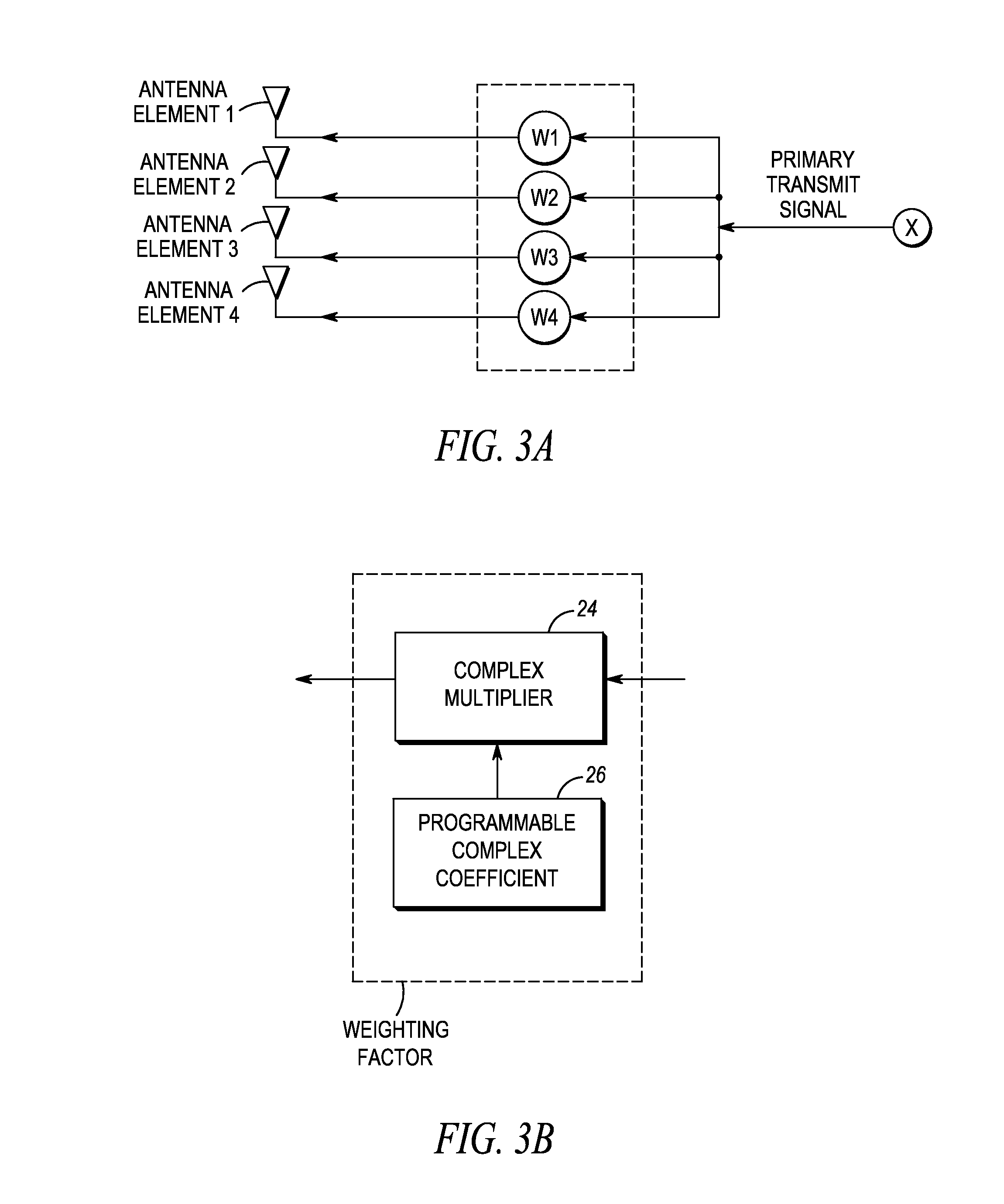
[0023]The present disclosure relates to a radio frequency (RF) identification (RFID) tag reading system for estimating bearings of RFID tags associated with items in a controlled area, of particular benefit when the RFID tags return receive signals whose power is below a predetermined threshold due to such real-world conditions as multi-path reflections, destructive signal interference, ambient temperature variations, etc. The controlled area may be a retail store, a warehouse, or any other confined or open area in which RFID-tagged items are to be monitored or located. The system includes one or more RFID readers each having a plurality of antenna elements, e.g., a beamforming array, preferably mounted overhead and arranged about a vertical axis or plumb line; a plurality of RF transceivers; and a controller or programmed microprocessor operatively connected to the transceivers, and operative for controlling the transceivers.

[0024]The controller executes a tag processing module ope...


PUM


Abstract

An RFID tag reading system and method estimate bearings of RFID tags. When the RSSI of a primary and / or secondary RFID receive signal is below a threshold, a primary receive beam is steered in a limited scan to an array of locations distributed around the location at which the RSSI of the primary receive signal is a maximum, and the RSSI of the primary receive signal is recorded at each location. The recorded RSSIs are processed to determine an effective weighted center of distribution of the recorded RSSIs, and the bearing for the tag based on the weighted center of distribution is thus estimated.

Description

BACKGROUND OF THE INVENTION[0001]The present disclosure relates generally to a system for, and a method of, estimating bearings of radio frequency (RF) identification (RFID) tags associated with items located in a controlled area, especially when the tags return RFID receive signals whose power is below a predetermined threshold due to such real-world conditions as multi-path reflections, destructive signal interference, ambient temperature variations, etc.[0002]Radio frequency (RF) identification (RFID) technology is becoming increasingly important for logistics concerns, material handling and inventory management in retail stores, warehouses, distribution centers, buildings, and like controlled areas. An RFID system typically includes an RFID reader, also known as an RFID interrogator, and preferably a plurality of such readers distributed about the controlled area. Each RFID reader interrogates at least one RFID tag, and preferably many more RFID tags, in its coverage range. Each...

Claims


Application Information

Patent Timeline
IPC IPC(8): G01S3/28G01S3/04
CPCG01S3/046G01S3/28G01S3/40G01S13/68G01S13/75G06K7/10099G01S13/878
Inventor SWOPE, CHARLES B.BEKRITSKY, BENJAMIN J.
Owner SYMBOL TECH LLC
Why Eureka
Try Eureka