Optical module for vibrating light beam

Active Publication Date: 2016-04-14
SAMSUNG DISPLAY CO LTD
View PDF3 Cites 9 Cited by
  • Summary
  • Abstract
  • Description
  • Claims
  • Application Information

AI Technical Summary

Benefits of technology

[0009]Aspects of one or more embodiments of the present invention include an optical module for vibrating a light beam capable of contact

Problems solved by technology

Because an optical system is highly sensitive to vibration, vibrations may induce poor beam alignment.
As a result, a light beam, such as a laser beam, needs to be regularly realigned, thereby having an adverse effect on the system and the proce

Method used


Image

  • Optical module for vibrating light beam
  • Optical module for vibrating light beam
  • Optical module for vibrating light beam

Examples


Embodiment Construction

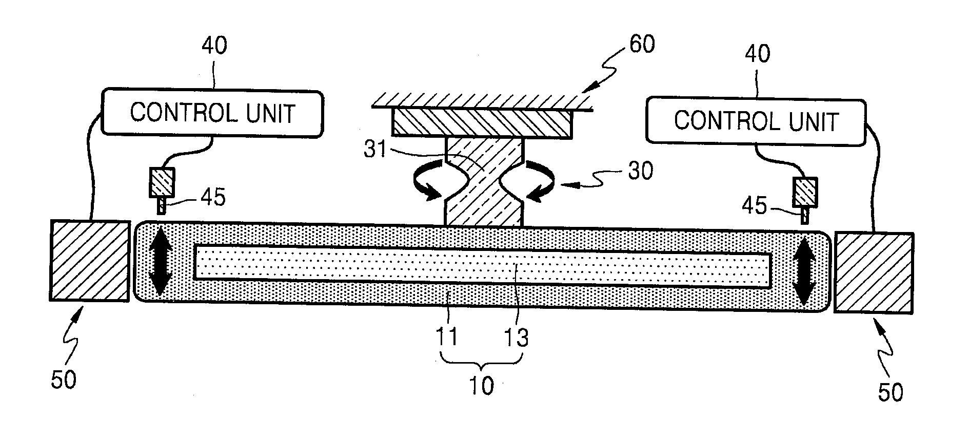
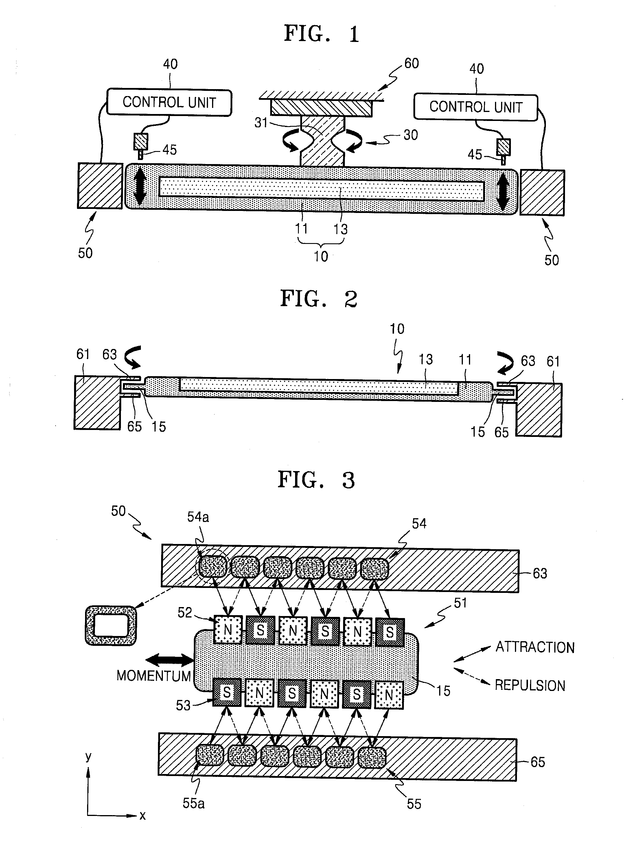
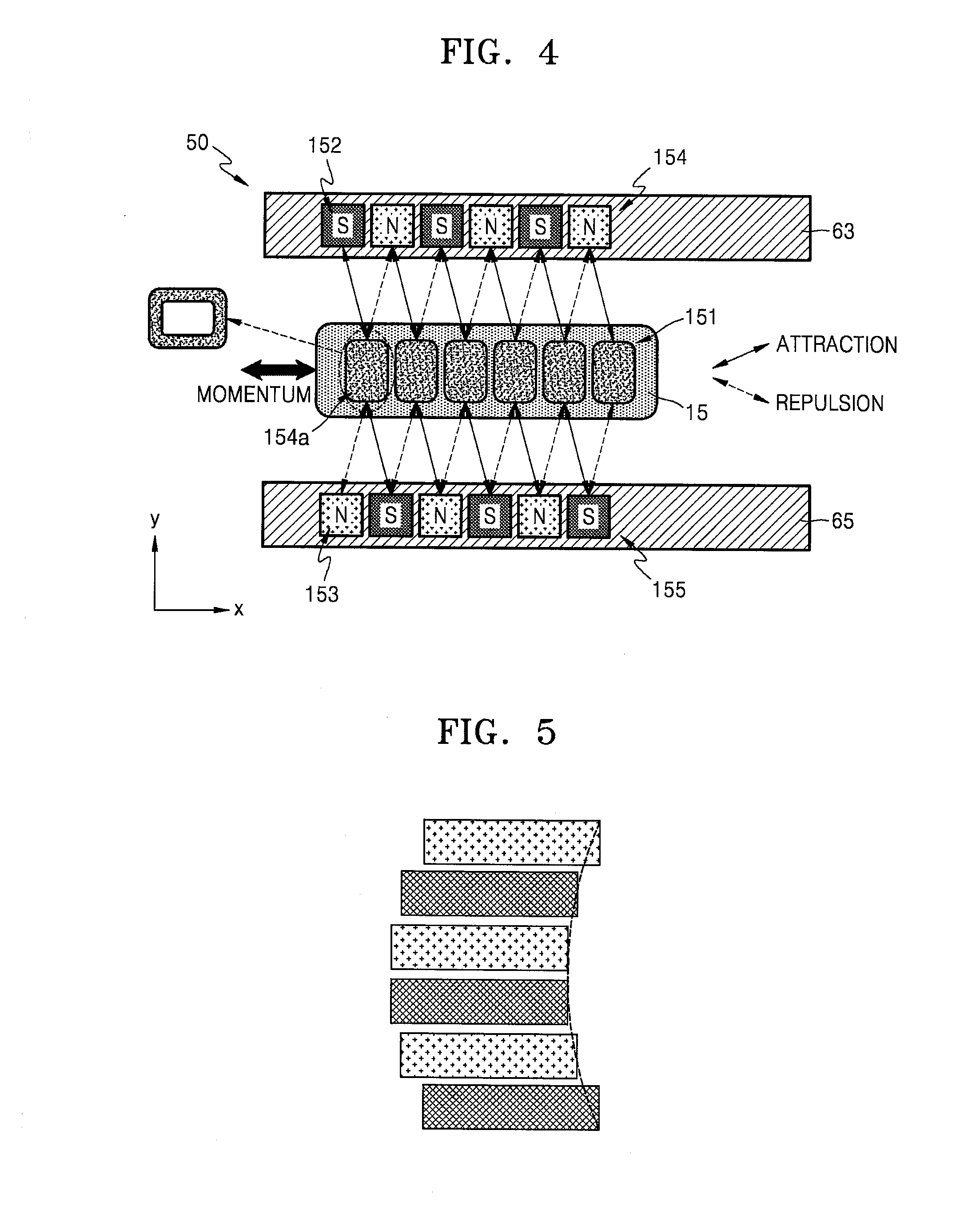
[0041]Reference will now be made in detail to embodiments, examples of which are illustrated in the accompanying drawings, wherein like reference numerals refer to like elements throughout. The present embodiments may have different forms and should not be construed as being limited to the descriptions set forth herein. Accordingly, the embodiments are merely described below, by referring to the figures, to explain aspects of the present description.

[0042]It will be understood that although the terms “first,”“second,” etc. may be used herein to describe various components, these components should not be limited by these terms. These terms are only used to distinguish one component from another.

[0043]As used herein, the singular forms “a” and “an” are intended to include the plural forms as well, unless the context clearly indicates otherwise.

[0044]It will be further understood that the terms “includes,”“including,”“comprises,” and / or “comprising,” when used herein, specify the prese...


PUM


Abstract

An optical module includes a mirror unit including a mirror holder and a mirror on the mirror holder, the mirror holding including a first plate; a center guide supporting the mirror unit; and an actuator configured to rotate the mirror unit about a rotation axis. The actuator includes a first actuator at the first plate and second and third actuators at second and third plates, respectively, and spaced from each other in a direction parallel to the rotation axis, and the first actuator is configured to be acted upon by the second and third actuators to rotate the mirror unit about the rotation axis.

Description

CROSS-REFERENCE TO RELATED APPLICATION[0001]This application claims priority to and the benefit of Korean Patent Application No. 10-2014-0135965, filed on Oct. 8, 2014 in the Korean Intellectual Property Office, the disclosure of which is incorporated herein in its entirety by reference.BACKGROUND[0002]1. Field[0003]Aspects of one or more embodiments of the present invention relate to an optical module for vibrating a light beam.[0004]2. Description of the Related Art[0005]An optical component, such as a lens or a mirror, is generally installed after being fixed to a mount. For a square vibration mirror, the mount generally has a rotation axis about a center of the mount, and the mirror is led to rotate around (about) the rotation axis by applying a mechanical force to an edge of the mount. Alternatively, the rotation axis may be at an edge of the mount, and the mirror may be vibrated by applying a mechanical force to the opposite edge of the mount.[0006]As described above, to form ...

Claims


Application Information

Patent Timeline
IPC IPC(8): G02B26/08G02B27/64
CPCG02B27/646G02B26/0816G02B26/085G02B6/3584G02B7/18
Inventor KIM, KYUBUMMYOUNG, SEUNGHORYU, JEKILOH, WONHEE
Owner SAMSUNG DISPLAY CO LTD
Why Eureka
Try Eureka