Device for Fluid Sampling

a fluid sampling and fluid technology, applied in the field of fluid sampling, can solve the problems of high price and high maintenance costs, inconvenient and high price and maintenance costs of adsorbed residues or residual gas, and achieve the effect of convenient storage, transportation and/or mailing

Active Publication Date: 2011-08-18
NEXTTEQ
View PDF14 Cites 8 Cited by
  • Summary
  • Abstract
  • Description
  • Claims
  • Application Information

AI Technical Summary

Benefits of technology

[0039]In a specific embodiment, at least a central portion of each of the panels is permanently adhered to the flexible sampling bag's sides with an appropriate adhesive. The size of the adhered spot may be approximately ⅓ of the surface area one bag wall but may vary as desired. The panels may comprise means for biasing the panels away from each other, handles of sof

Problems solved by technology

Any adsorbed residue or residual gas may contaminate any prepared fluid mixture or sample of fluid put in a poorly prepared bag.
The disadvantages of containers with rigid walls include their extremely high price and expensive maintenance; they are bulky and, thus, their storage, transportation, and mailing costs are expensive; they have to be over pressurized when delivery of gas vapors or mixtures is needed; and completely vacuumed before used for fluid sampling.
Another drawback of sampling with containers with rigid walls is that after removing a portion of the sample from the container, the pressure in the canister may be reduced below atmospheric pressure and additional carrier gas (noble gas for example) may be added to increase the pressure back to atmospheric pressure.
A small sampling pump cannot create a sufficient vacuum within the container; therefore, strong specialized vacuum pumps are needed.
There are advantages and disadvantages to using this method with sampling bags.
The disadvantages include the cost, inaccuracy, and potential contamination from using an external pump to deliver

Method used


Image

  • Device for Fluid Sampling
  • Device for Fluid Sampling
  • Device for Fluid Sampling

Examples


Embodiment Construction

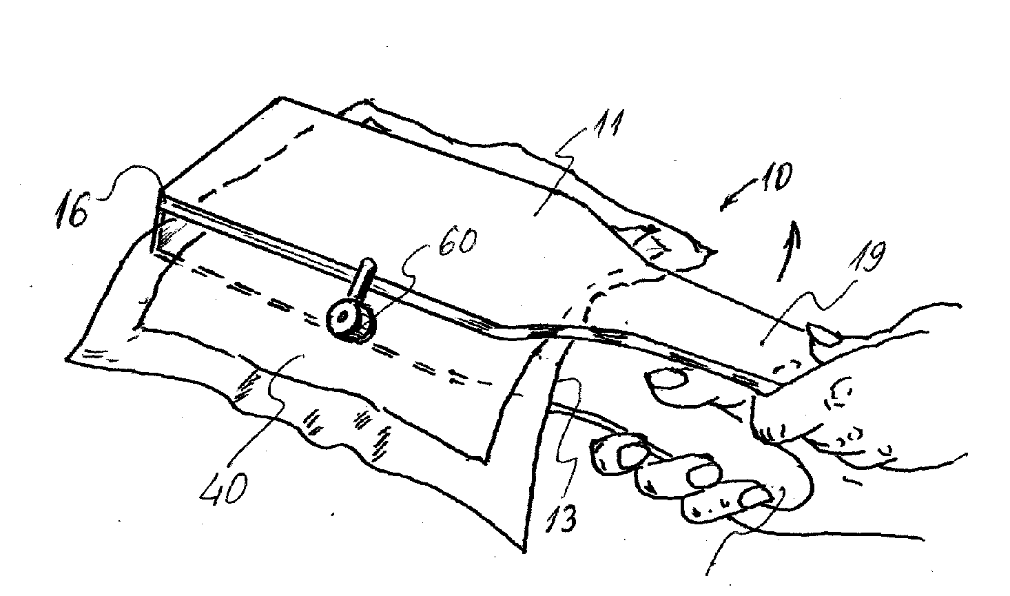
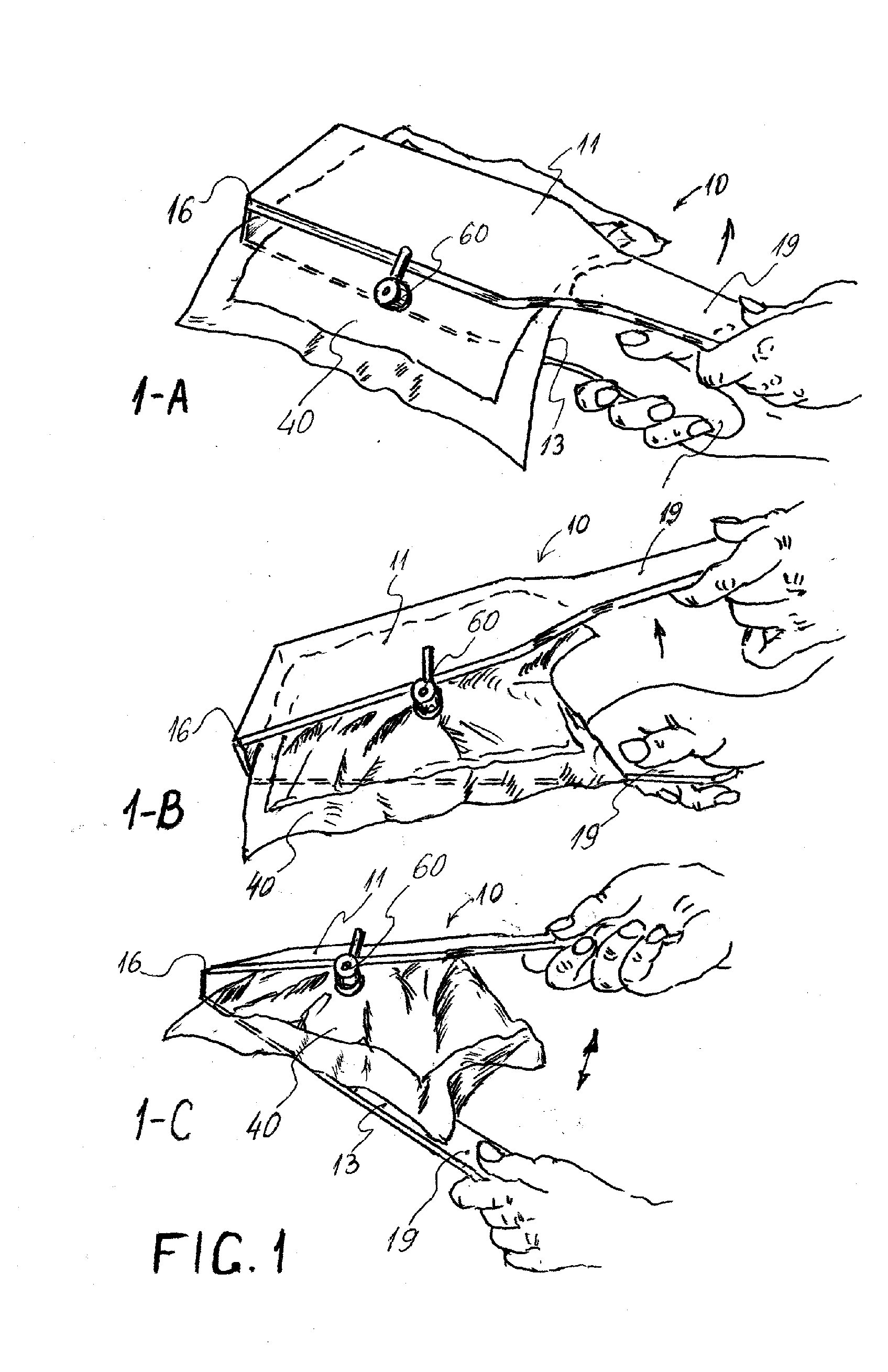
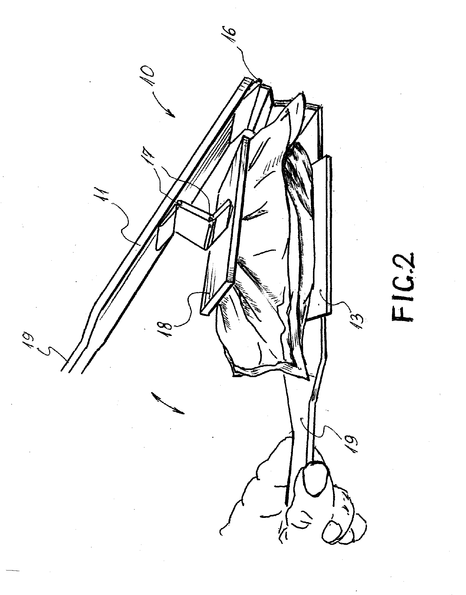
[0051]Embodiments of the sampling device comprise two panels capable of assisting with inflating and deflating the sampling or other bag. One embodiment of the sampling device is shown on FIG. 1, the sampling device 10 comprises an top panel 11 and a bottom panel 13. In this embodiment, the top panel 11 and bottom panel 13 have a substantially rectangular shape and area sufficient to cover a substantial portion of the surface of the sampling bag 40. The top panel 11 and bottom panel 13 have one of their ends rotatably attached with a hinged connection 16. The other ends of the top panel 11 and bottom panel 13 are shaped as handles 19 for easy operation by hands. Other embodiments of the sampling device may comprise panels having other handle designs. The inner surface of the rotatably connected top panel 11 and bottom panel 13 at least partially comprises an adhering means 30 capable of at least temporary adhesion to one surface of the sampling bag 40. The material for adhering mean...


PUM


Abstract

The disclosure is directed to a device for fluid sampling. The device may have two panels that are or may be adhered, attached or otherwise connected to opposite sides of a sampling bag having flexible walls. The panels may be used for conveniently inflating or deflating the sampling bag and obtaining fluid samples.

Description

RELATED APPLICATIONS[0001]This patent applications claims priority under 35 U.S.C. §119 to U.S. Provisional Patent Application Ser. No. 61 / 305,001 filed on Feb. 16, 2010 which is incorporated by reference in its entirety.FIELD OF THE INVENTION[0002]Embodiments of the present invention is directed to sampling of fluids and more particularly to air sampling with containers with flexible walls, referred to as sampling bags. Further, embodiments of the sampling bag may comprise panel attached to the exterior of the sampling bags. The panels may further comprise a handle configured to allow the sampling bags to be inflated and deflated by hand.BACKGROUND OF THE INVENTION[0003]Conventional containers for fluids may have rigid walls or flexible walls. Containers with rigid walls have a defined permanent volume for containing fluids and containers with flexible walls have variable or changeable volumes. Conventional containers include, but are not limited to, bottles, canisters and bags. Su...

Claims


Application Information

Patent Timeline
IPC IPC(8): G01N1/12
CPCG01N1/14G01N2001/1427G01N1/24
Inventor MIHAYLOV, GUEORGUITRUEX, BRYAN
Owner NEXTTEQ
Why Eureka
Try Eureka