Vibration-restraining control apparatus for vehicle

a control device and vehicle technology, applied in electric/magnetic computing, instruments, analogue processes for specific applications, etc., can solve the problem that the control system cannot correct the driving torque to suppress the sprung vibration of the vehicle properly, and achieve the effect of improving the driving for

Inactive Publication Date: 2013-04-11
NISSAN MOTOR CO LTD
View PDF1 Cites 10 Cited by
  • Summary
  • Abstract
  • Description
  • Claims
  • Application Information

AI Technical Summary

Benefits of technology

[0007]The reliability of the sprung vibration estimated from the wheel speed and the reliability of the sprung vibration estimated from the driving / braking torque vary in dependence on the traveling state. Therefore, the control system can correct the driving force more adequately by varying the weight of the proper vibration suppressing torque and the weight of the improper vibration suppressing torque.

Problems solved by technology

Therefore, in a driving scene where the deviation of the wheel speed sensed by a wheel speed sensor from the actual wheel speed becomes greater, the vibration suppressing torque is calculated from the wheel speed deviated from the actual wheel speed, and therefore the control system is unable to correct the driving torque to suppress the sprung vibration of the vehicle properly.

Method used


Image

  • Vibration-restraining control apparatus for vehicle
  • Vibration-restraining control apparatus for vehicle
  • Vibration-restraining control apparatus for vehicle

Examples


embodiment 1

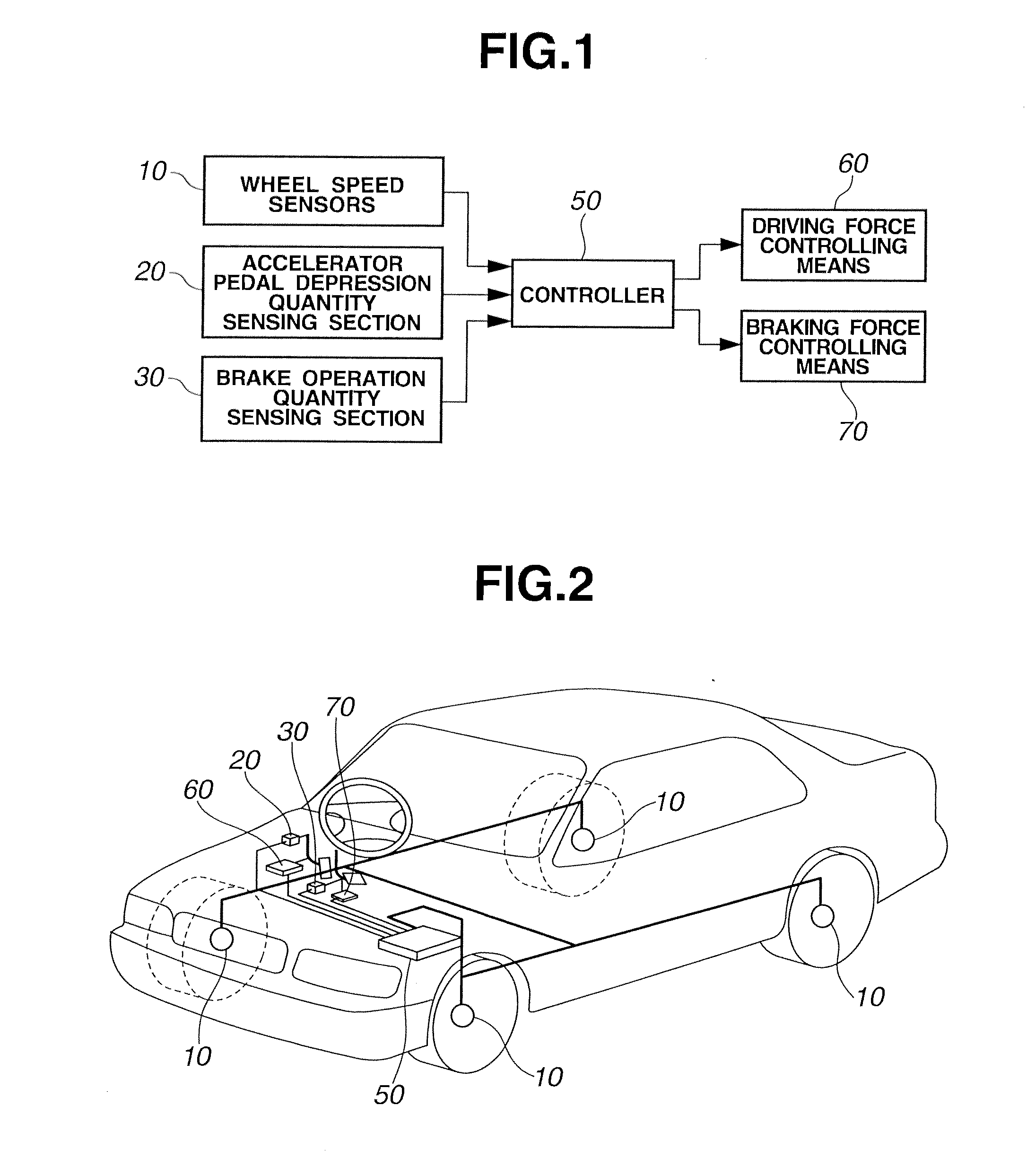
[0027]FIG. 1 is a system view showing the structure of a vibration damping or suppressing apparatus according to an embodiment 1. FIG. 2 is a structure view showing a vehicle equipped with the vibration damping apparatus. First, explanation is directed to the structure of the vibration damping apparatus. Wheel speed sensors 10 sense the wheels speeds of respective wheels of the vehicle from the rpms of the respective wheels. An accelerator pedal depression quantity sensing section 20 senses an accelerator opening degree APO representing the depression quantity of an accelerator pedal by the driver. A brake operation quantity sensing section 30 senses a brake operation quantity S_b by the driver (such as a brake pedal stroke quantity or a depressing force on a brake pedal).

[0028]A controller 50 delivers control signals to a driving force controlling means or device 60 and a braking force controlling means or device 70 which are an actuator or actuators of the vibration suppressing ap...

embodiment 2

[0078]Following is explanation on a second embodiment. Since the basic construction is the same as the first embodiment, the following explanation is directed only to points different from the first embodiment. FIG. 13 is a flowchart showing a weighting coefficient setting process according to the second embodiment.

[0079]At a step S300-1, the controller acquires or obtain an operating state of an brake actuator control (such as VDC, TCS, ABS, EBD etc.). VDC is an abbreviation of vehicle dynamics control which is a control to stabilize a vehicle cornering behavior (yaw rate, etc.). TCS is an abbreviation of traction control system to restrain slip due to excessive torque applied to a driving wheel. ABS is an abbreviation of anti-lock brake system to avoid wheel lock at the time of hard braking. EBD is an abbreviation of electronic brake force distribution system to optimize the front and rear wheel brake force distribution to prevent rear wheel lock at the time of braking. Each of th...


PUM


Abstract

Predetermined weights are assigned, in accordance with a traveling state, to a first correction toque to suppress a sprung vibration of the vehicle in accordance with a wheel speed, and a second correction toque to suppress the sprung vibration of the vehicle in accordance with a driving/braking torque. With this configuration, it becomes possible to calculate the vibration suppressing torque corresponding to the traveling state.

Description

TECHNICAL FIELD[0001]The present invention relates to a vibration restraining or damping or suppressing control device or apparatus for restraining vibrations produced in a vehicle.BACKGROUND ART[0002]A patent document 1 discloses a vibration suppressing technique to calculate a vibration suppressing torque for suppressing sprung vibrations by using, as input variables, a driving torque and a wheel speed, and to restrain sprung vibration of the vehicle.[0003]However, according to the technique disclosed in the patent document 1, the vibration suppressing torque is calculated from both of the driving torque and the wheel speed as input variable, irrespective of the traveling state of the vehicle. Therefore, in a driving scene where the deviation of the wheel speed sensed by a wheel speed sensor from the actual wheel speed becomes greater, the vibration suppressing torque is calculated from the wheel speed deviated from the actual wheel speed, and therefore the control system is unabl...

Claims


Application Information

Patent Timeline
Patent Type & Authority Applications(United States)
IPC IPC(8): B60W10/04F16F15/00B60W10/18B60L15/20B60W10/06B60W10/184B60W30/00B60W30/18F16F15/02
CPCB60L2270/145B60W10/06B60W10/188B60W30/20B60W2520/28B60W2540/10F16F15/002B60W2710/0666B60W2710/182B60W2720/16Y02T10/7258B60W10/04B60W10/18B60W2540/12Y02T10/72
Inventor OHTA, MITSUNORIYOSHIZAWA, MASAHIKOSHIOZAWA, YUUKIKOBAYASHI, YOSUKEITOH, AKIHIRO
Owner NISSAN MOTOR CO LTD
Why Eureka
Try Eureka