Supercharge Your Innovation With Domain-Expert AI Agents!

Projector and method for mixing light by a projector

a projector and light technology, applied in the field of projector and light mixing method, can solve problems such as quality loss

Inactive Publication Date: 2016-04-14
QISDA OPTRONICS (SUZHOU) CO LTD +1
View PDF12 Cites 7 Cited by
  • Summary
  • Abstract
  • Description
  • Claims
  • Application Information

AI Technical Summary

Benefits of technology

The present invention relates to a method and apparatus for mixing light using a projector. The technical effects of this invention include improved color accuracy and consistency, as well as reduced energy consumption and improved efficiency. The method involves inducing a first light using a solid state light emitter, and then stimulating phosphors using the first light to induce a second light. The second light is then filtered using a blue light filter layer to induce a third light with specific coordinates in the CIE 1931 color space. The apparatus includes a solid state light emitter, a phosphorous color wheel, a shield, and a blue light filter layer. The shield covers the light emitting diode, and the phosphores are disposed on the shield or on a separate shield. The blue light filter layer is either on or separated from the shield and filters the second light to induce a third light with specific coordinates in the CIE 1931 color space.

Problems solved by technology

Due to the concerns of pollutants caused by the mercury lamps, projectors using mercury lamps as light sources can be contradictory to the mainstream sense of environmental protection.
Since the projector 100 uses the purplish-blue light as the required color light for displaying the image, the purplish image usually becomes an issues which causing the quality loss.

Method used


Image

  • Projector and method for mixing light by a projector
  • Projector and method for mixing light by a projector
  • Projector and method for mixing light by a projector

Examples


Embodiment Construction

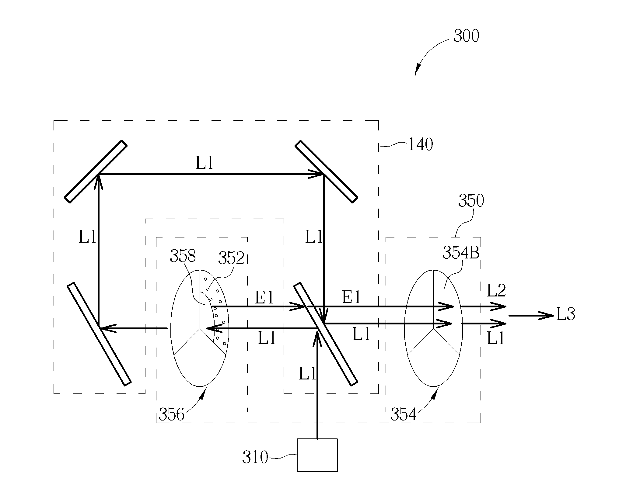
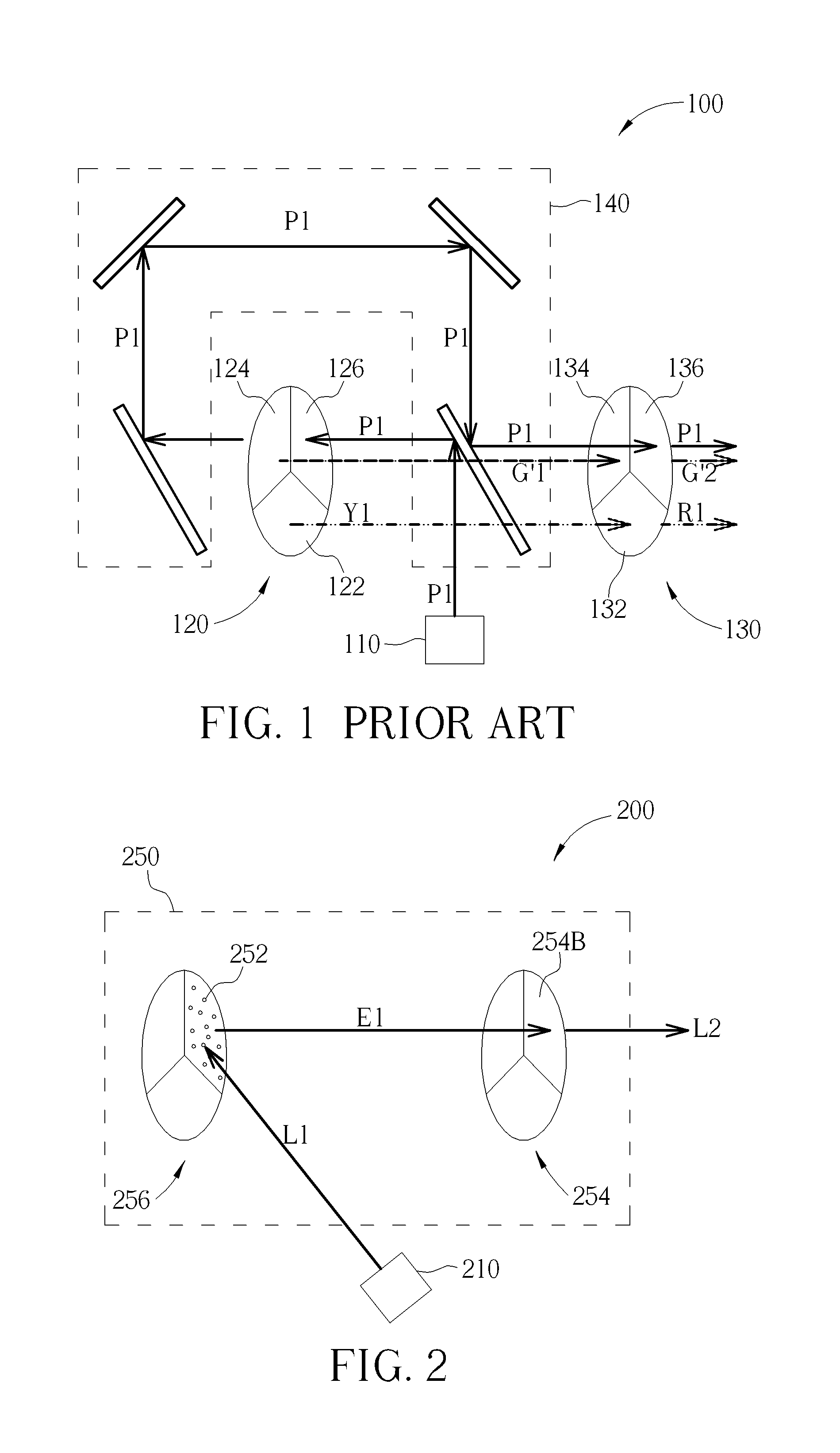
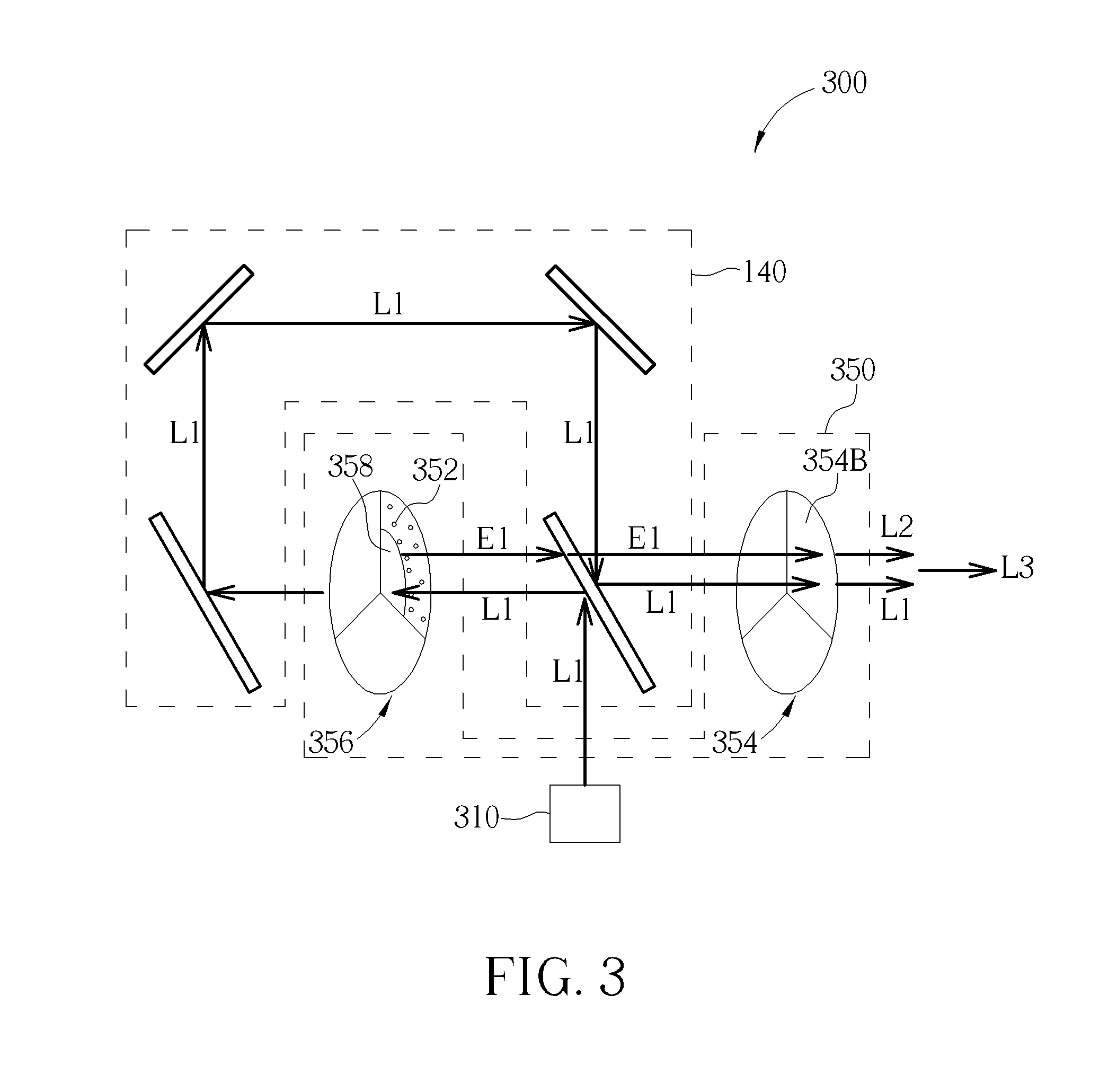
[0024]FIG. 2 shows a projector 200 according to one embodiment of the present invention. The projector 200 includes a solid state light emitter 210 and a light induction unit 250. The solid state light emitter 210 can be configured to emit a first light L1. The light induction unit 250 can be configured to receive the first light L1 and to induce a second light L2. Part of the first light L1 can pass through the light induction unit 250 and can mix with the second light L2 to make a third light L3. The coordinates of each of the lights on the Diagram of the CIE 1931 color space according to the Commission Internationale de L'éclairage (CIE) can be called as the CIE coordinates of each of the lights for the purpose of convenient. The CIE coordinates of the third light L3 can be represented as (x3, y3) and can be within the range of:

0.14≦x3≦0.15

0.04≦y3≦0.09

[0025]That is, the third light L3 mixed by the first light L1 and the second light L2 can be a blue light. Due to the limitation o...


PUM


Abstract

A method for mixing light in a projector includes mixing first light emitted by a solid state light emitter and second light into third light. The coordinates (x3, y3) of the third light in the Diagram of the CIE 1931 color space are within the range of 0.14≦x3≦0.15 and 0.04≦y3≦0.09.

Description

BACKGROUND OF THE INVENTION[0001]1. Field of the Invention[0002]This invention is related to a method for mixing light by a projector, and more particularly, a method for mixing light by a projector using a solid state light emitter.[0003]2. Description of the Prior Art[0004]Due to the concerns of pollutants caused by the mercury lamps, projectors using mercury lamps as light sources can be contradictory to the mainstream sense of environmental protection. Therefore a projector using a solid state light emitter, such as a light emitting diode or laser diode, to stimulate the phosphors as a light source has become a popular selection.[0005]FIG. 1 shows a projector 100 according to prior art. The projector 100 includes a solid state light emitter 110, a phosphorous color wheel 120, a filter color wheel 130, and a light direction device 140. The solid state light emitter 10 is a light emitting diode for emitting a purplish-blue light P1. The light direction device 140 can direct the pu...

Claims


Application Information

Patent Timeline
Patent Type & Authority Applications(United States)
IPC IPC(8): H04N9/31G02B26/00
CPCH04N9/3111H04N9/3161G02B26/008H04N9/3114H04N9/3158G03B21/204G03B21/2066
Inventor WANG, KAI-JING
Owner QISDA OPTRONICS (SUZHOU) CO LTD
Features
  • R&D
  • Intellectual Property
  • Life Sciences
  • Materials
  • Tech Scout
  • Unparalleled Data Quality
  • Higher Quality Content
  • 60% Fewer Hallucinations
Learn More