

Optical element
a technology of optical elements and optical components, applied in the field of optical components, can solve the problems of deterioration of the function of light-diverging optical components, and achieve the effect of reducing the color difference between directions more effectively
- Summary
- Abstract
- Description
- Claims
- Application Information
AI Technical Summary
Benefits of technology
Problems solved by technology
Method used
Image

Examples
example 1
[0068]In the present example, the distance T between P0 and O2 is as below.
T=5.500 mm
The distance h between P0 and O1 is as below.
h=4.450 mm
[0069]The shape of the exit surface 103 is represented by the following equations.
When 0≦rmax,
z=cr21+1-(1+k)c2r2+∑i=1NAiri.(1)
When 6.8≦r≦8.5,
z=cr21+1-(1+k)c2r2+∑i=1NAiri+-ωrt(Bsin[πKrt]).(2)
The function z of r is defined such that Equation (1) and Equation (2) are continuously connected.
The following relationships hold.
c=1 / R
r2=x2+y2
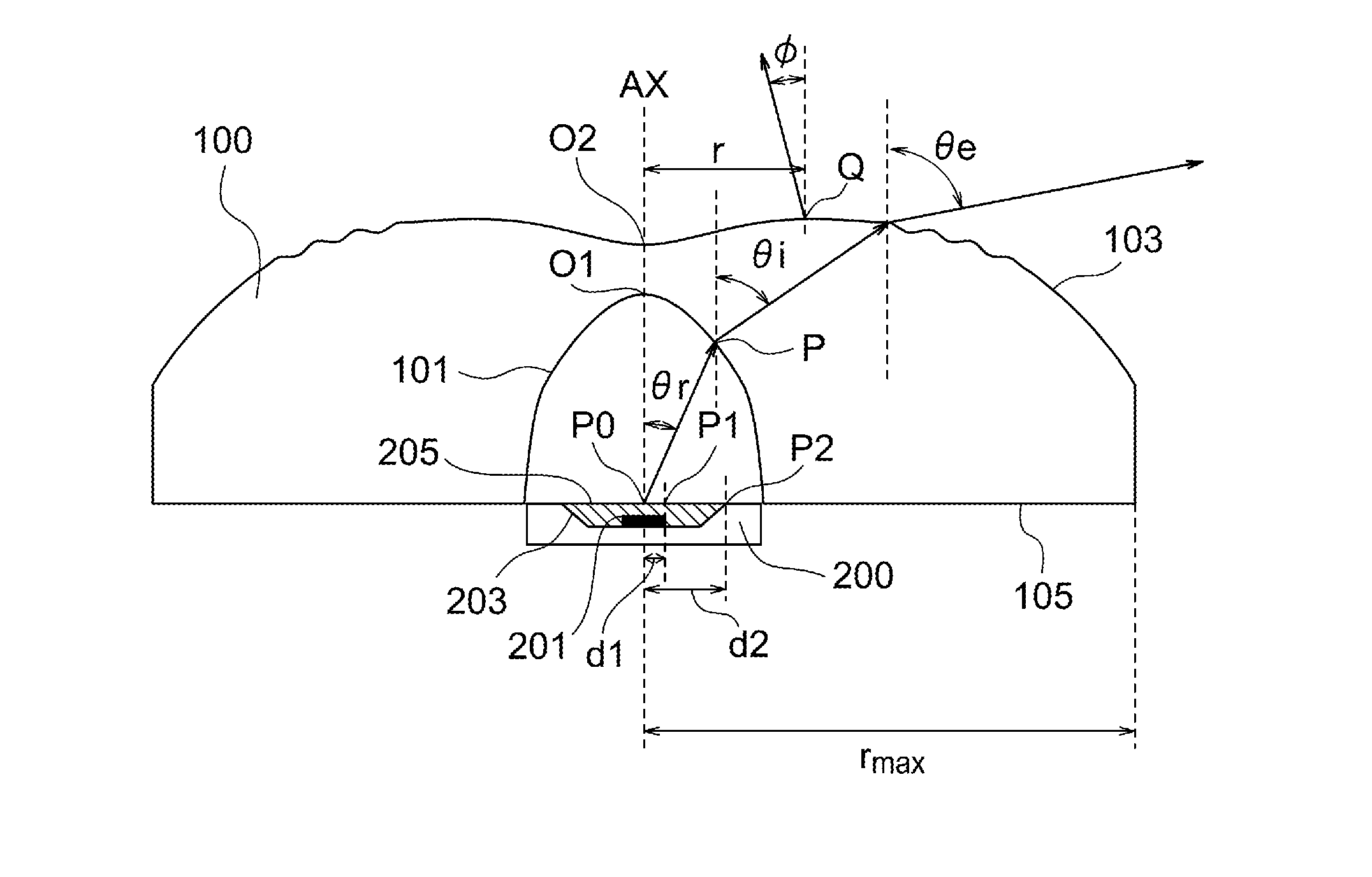
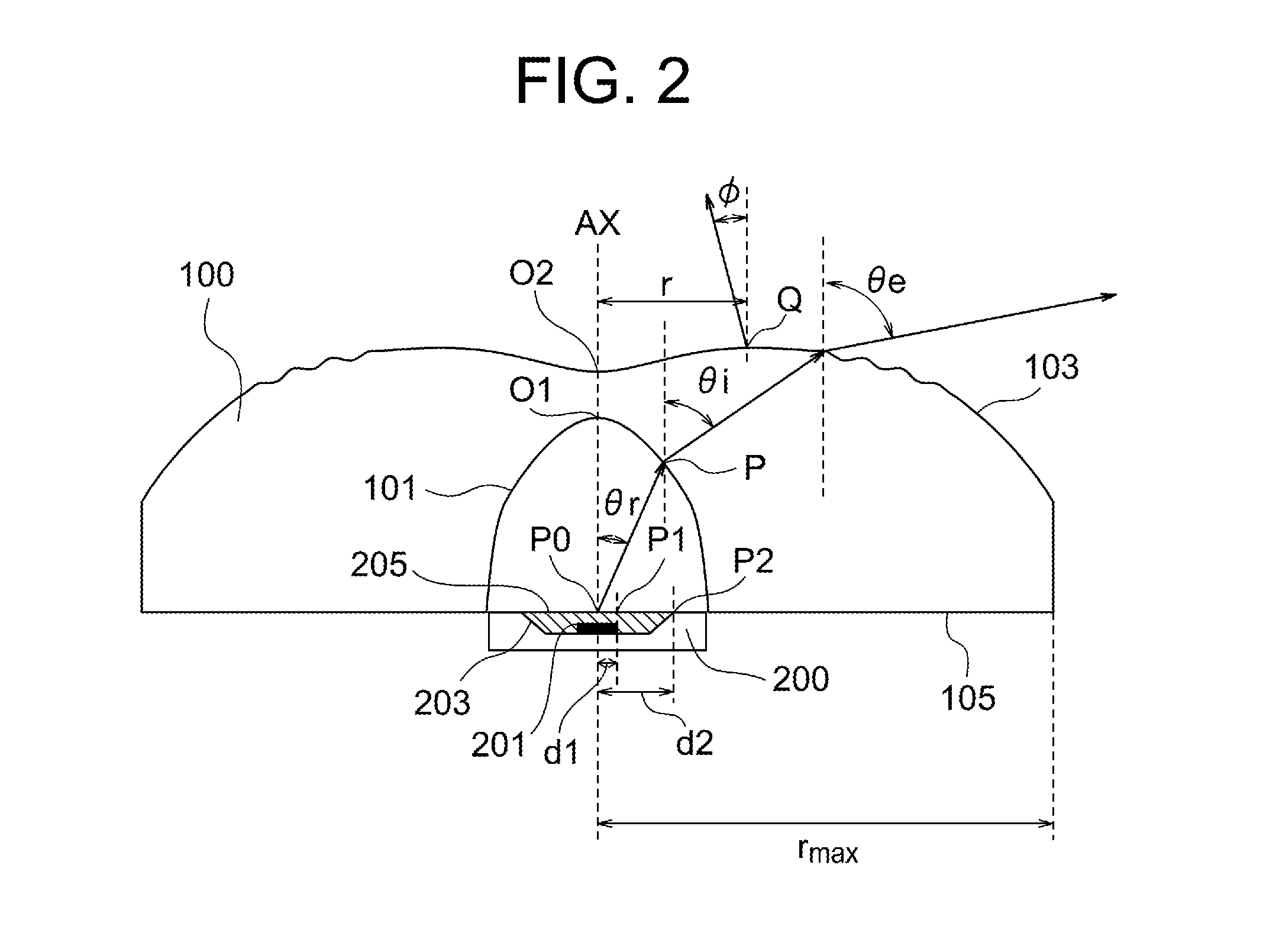
“r” represents distance from the central axis AX. “rmax” represents the maximum value of r in the area of the exit surface, and rmax=9.25 (mm). “z” represents coordinate in the direction of the central axis AX with respect to the point of intersection O2 of the exit surface with the central axis AX. “c” represents curvature, “R” represents radius of curvature, “k” represents conic constant and “Ai” represents aspheric coefficient. “n” represents the ratio of the circumstance of a circle to the diameter, “B” represen...
example 2
[0091]In the present example, the distance T between P0 and O2 is as below.
T=5.536 mm
The distance h between P0 and O1 is as below.
h=4.536 mm
[0092]The shape of the exit surface 103 is represented by the following equations.
When 0≦rmax,
z=cr21+1-(1+k)c2r2+∑i=1NAiri.(1)
When 7.0≦r≦8.5,
z=cr21+1-(1+k)c2r2+∑i=1NAiri+-ωrt(Bsin[πKrt]).(2)
The function z of r is defined such that Equation (1) and Equation (2) are continuously connected.
The following relationships hold.
c=1 / R
r2=x2+y2
“r” represents distance from the central axis AX. “rmax” represents the maximum value of r in the exit surface, and rmax=9.25 (mm). “z” represents coordinate in the direction of the central axis AX with respect to the point of intersection O2 of the exit surface with the central axis AX. “c” represents curvature, “R” represents radius of curvature, “k” represents conic constant and “Ai” represents aspheric coefficient. “n” represents the ratio of the circumstance of a circle to the diameter, “B” represents amplitude...
example 3
[0114]In the present example, the distance T between P0 and O2 is as below.
T=5.555 mm
The distance h between P0 and O1 is as below.
h=4.555 mm
[0115]The shape of the exit surface 103 is represented by a spline curve of order 3 for the following group of points. A spline curve of order 3 is a smooth curve which passes through given plural control points and which is formed by third-degree polynomials, each of which interpolates each segment between two adjacent control points and is determined to be continuous at the control points.
[0116]Table 7 shows the group of points of the spline curve of order 3. “r” represents distance from the central axis AX. “rmax” represents the maximum value of r in the area of the exit surface, and rmax=9.25 (mm). “z” represents coordinate in the direction of the central axis AX with respect to the point of intersection O2 of the exit surface with the central axis AX.
TABLE 7rZ0.0000.0000.1000.0030.2000.0100.3000.0230.4000.0390.5000.0581.0000.1752.0000.3873....
PUM
 Abstract
Description
Claims
Application Information