Eureka AIR delivers breakthrough ideas for toughest innovation challenges, trusted by R&D personnel around the world.

Focal-Plane Shutter for Camera and Digital Camera equipped therewith

a digital camera and camera technology, applied in the field of focal plane shutters for cameras and digital cameras equipped therewith, can solve the problems of increasing costs, increasing electric power consumption, and low flexibility in configuration, and achieves low cost of switching mechanism, low electric power consumption, and flexibility in configuration of actuators.

Inactive Publication Date: 2016-04-21
COPAL CO LTD
View PDF1 Cites 1 Cited by
  • Summary
  • Abstract
  • Description
  • Claims
  • Application Information

AI Technical Summary

Benefits of technology

The present invention is a focal plane shutter for a camera that allows for switching between imaging using a normally open system and imaging using a normally closed system. The switching mechanism includes an electromagnet and a stopping member with an engaging portion that can lock onto the first driving member for the leading blade. The direction of force from the electromagnet is switched in relation to the electric current being applied or removed, and the engagement portion can be locked or released to switch between the stopping member and the first driving member. This design reduces the cost and complexity of the switching mechanism, and also reduces electric power consumption. The stopping member can rotate and lock onto the engagement portion in either the repulsive or attractive direction, depending on the direction of the electric current being applied. This flexibility in design allows for a more cost-effective and flexible switching mechanism.

Problems solved by technology

However, the use of a solenoid and / or permanent magnet rotor in a switching mechanism, as in the focal plane shutter set forth in the JP '986 and the JP '060, increases the cost.
Moreover, the range of movement of the movable element in the permanent magnet rotor is limited, so the flexibility in the configuration is low.
Moreover, because there is switching of the electric current in two directions in the electromagnetic device, the electric power consumption is increased commensurately.

Method used


Image

  • Focal-Plane Shutter for Camera and Digital Camera equipped therewith
  • Focal-Plane Shutter for Camera and Digital Camera equipped therewith
  • Focal-Plane Shutter for Camera and Digital Camera equipped therewith

Examples


example

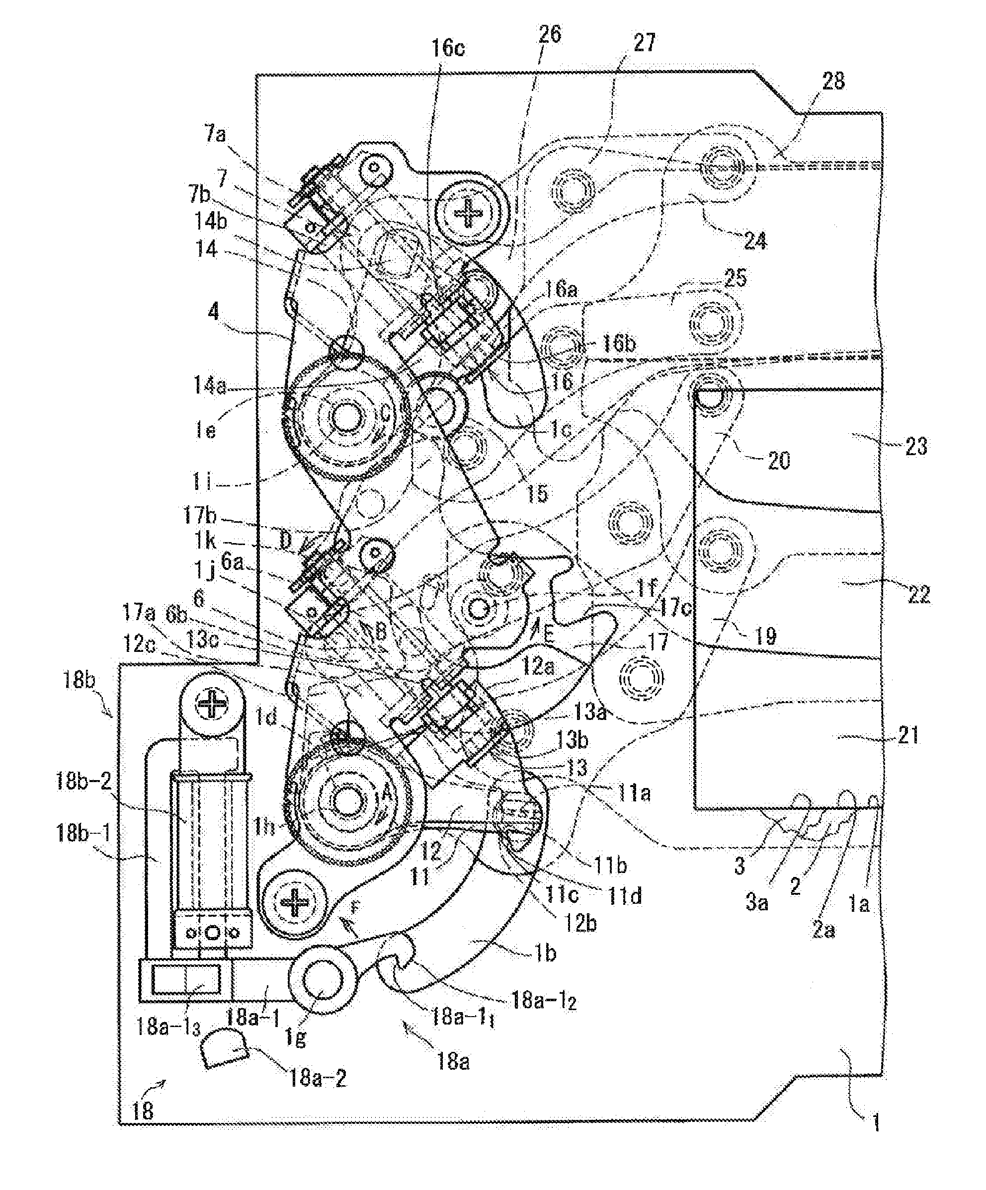
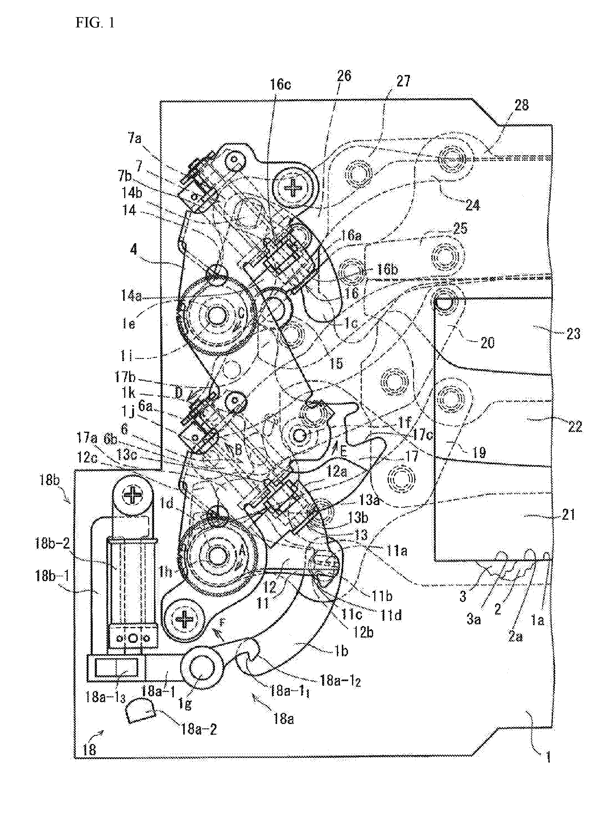
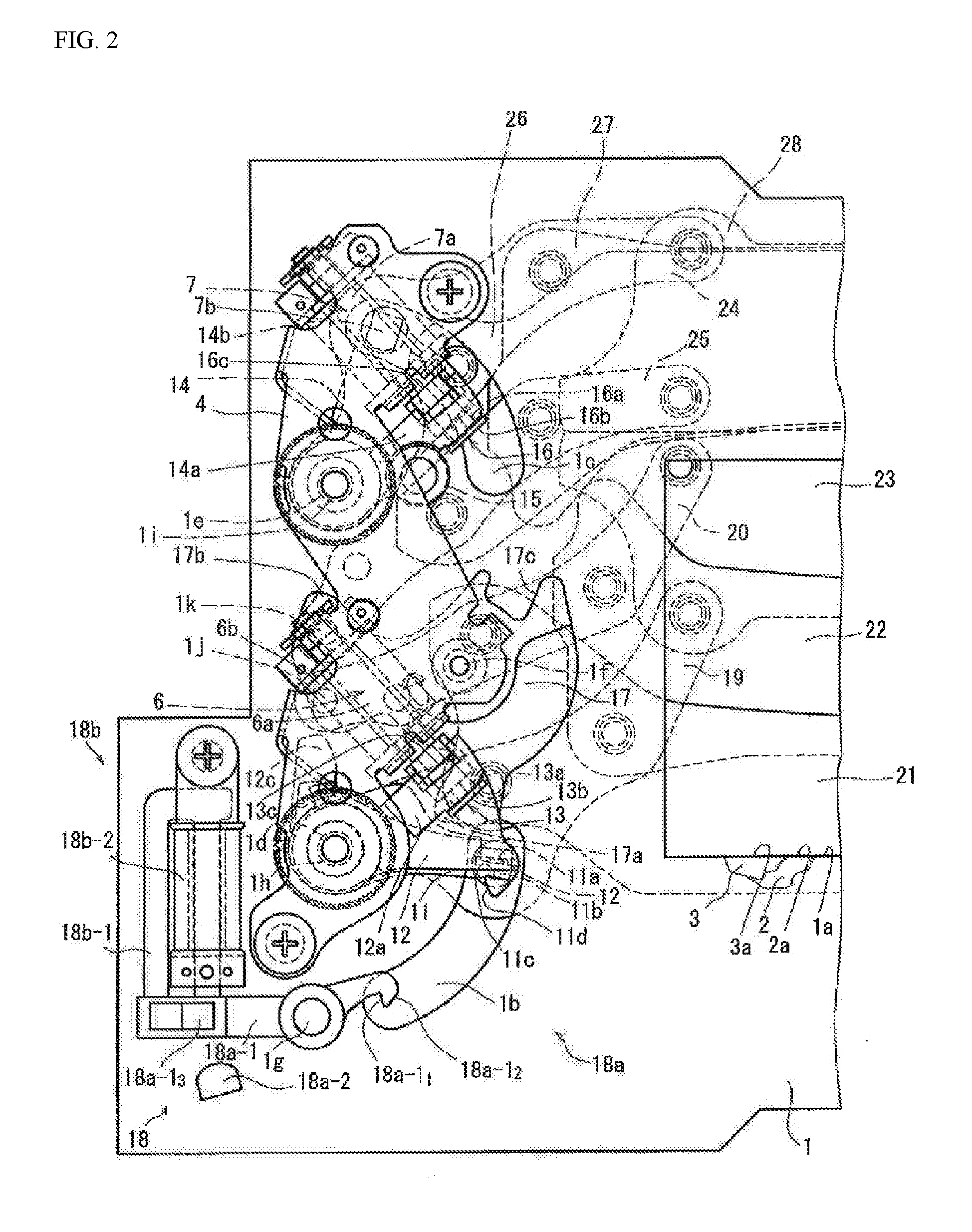
[0042]First the structure of Example according to the present invention will be explained using, primarily, FIG. 1 and FIG. 2. FIG. 1 is a plan view diagram enlarging the about half on the left side, when viewed from the photographic subject side, viewing a state wherein, when capturing an image in the normally open system in a focal plane shutter for a camera according to the Example according to the present invention, after the setting operations have been completed, the release button is pressed, a control lever moves out of the travel path for the engagement portion of the first driving member for the leading blade, the lock with the first driving member of the leading blade is unlocked, and the leading blade returns to the position that covers the exposure opening, after which the control lever has moved into the travel path of the engagement portion of the first driving member of the leading blade. Note that in the explanation of the present example, when the focal plane shutt...


PUM


Abstract

A focal plane shutter is provided with a switching mechanism having an electromagnet and a stopping member. The stopping member is provided with an engaging portion able to lock an engagement portion provided in a first driving member for a leading edge, and an operating portion wherein a direction of a force, in relation to the electromagnet, switches, in accordance with switching between an application and removal of an electric current in a single direction to the electromagnet, so as to move the engaging portion to a position wherein it is able to release locking of the engagement portion when the electric current is applied, and to move the engaging portion to a position wherein it is able to lock the engagement portion when the electric current is removed.

Description

CROSS REFERENCE TO RELATED APPLICATIONS[0001]This application is a continuation of U.S. patent application Ser. No. 14 / 497,414, filed Sep. 26, 2014, which claims the benefit of Japanese Patent Application No. 2013-201310, filed Sep. 27, 2013, each of which is incorporated by reference herein in its entireties.FIELD OF TECHNOLOGY[0002]The present invention relates to a focal plane shutter for a camera and to a digital camera equipped therewith.BACKGROUND[0003]At present, focal plane shutters are commonly used that employ imaging using a normally open system for a camera wherein, when capturing an image, one or more blade groups is driven to expose a photosensitive surface, and then, during standby, the image frame is opened, and the image is read in. Given this, in a focal plane shutter that employs image capturing using a normally open system, the use of a switching mechanism has been proposed to enable switching to image capturing in a normally closed system, wherein the image fram...

Claims


Application Information

Patent Timeline
Patent Type & Authority Applications(United States)
IPC IPC(8): G03B9/58G03B9/42H04N5/235
CPCG03B9/58G03B9/42H04N5/2353H04N23/50H04N23/73
Inventor TANAKA, YASUO
Owner COPAL CO LTD
Why Eureka
Eureka Blog
Learn More