Methods of forming a semiconductor circuit element and semiconductor circuit element

Active Publication Date: 2016-04-21
GLOBALFOUNDRIES US INC
View PDF3 Cites 24 Cited by
  • Summary
  • Abstract
  • Description
  • Claims
  • Application Information

AI Technical Summary

Benefits of technology

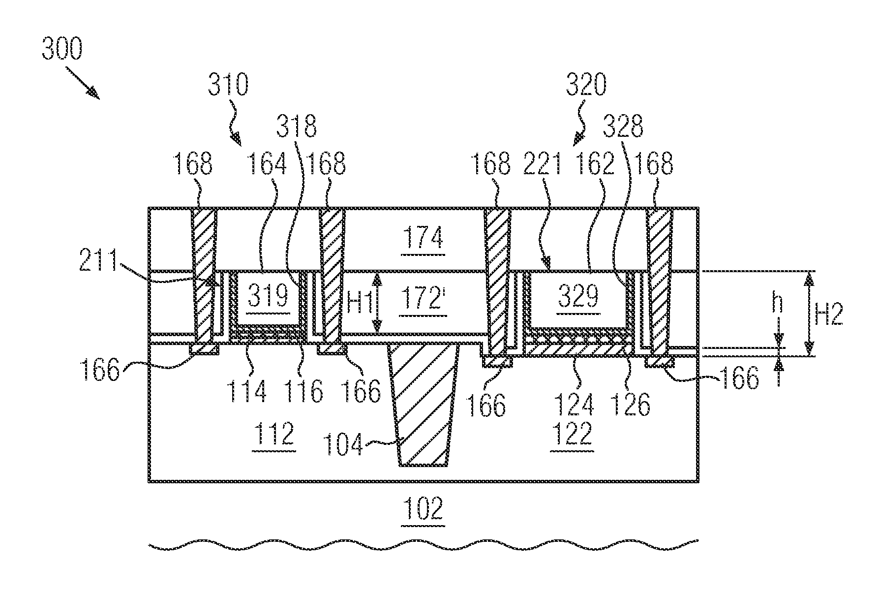
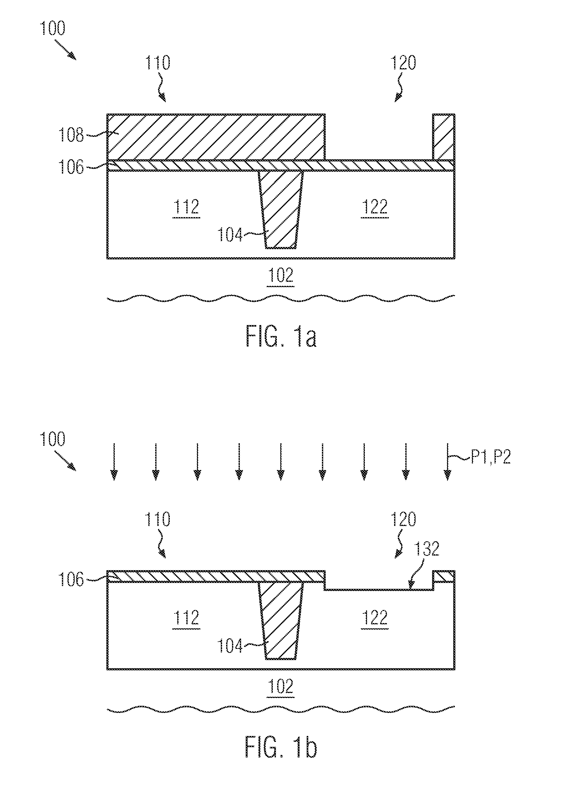
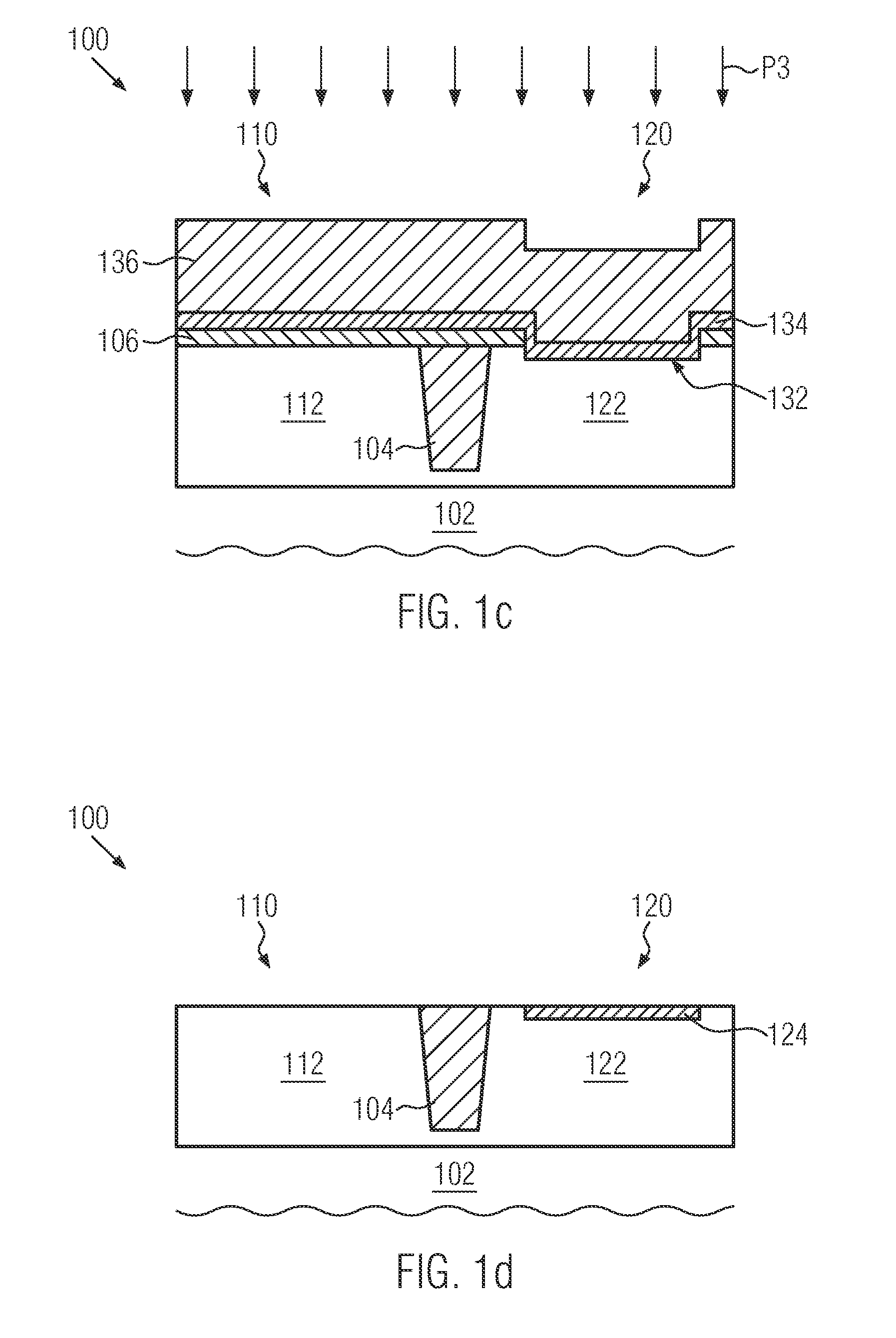
The present patent provides methods and structures for forming semiconductor circuit elements with different gate structures. The first gate structure includes a ferroelectric material, while the second gate structure includes a high-k material different from the ferroelectric material. The methods involve forming a recess in a semiconductor substrate, providing a ferroelectric material in the recess, and forming a high-k material over the substrate. The resulting semiconductor circuit elements have improved performance and reliability.

Problems solved by technology

Though a FeFET or a ferroelectric capacitor represent in theory very promising concepts for complex semiconductor devices, it is a difficult task to identify appropriate ferroelectric materials which are compatible with existing advanced manufacturing processes of complex devices, particularly at very small scales.
For example, commonly-known ferroelectric materials, such as PZT or perovskites, are not compatible with standard CMOS processes.
Although this stack of ferroelectric high-k material and logic high-k material shows ferroelectric properties, the speed and function of the FeFET devices is negatively affected by parasitic capacitances appearing in the stack.
This problem is present in FeFET integration, independent of whether a gate last or replacement gate technique or a gate first technique is employed.
Gate last or replacement gate techniques suffer the problem that the critical dimension of gate structures of FeFET devices is limited by the thick high-k layer of FeFET devices.
Furthermore, in gate last or replacement gate approaches close to the 28 nm technology node employing early nickel silicide, an activation anneal for ferroelectric high-k material is limited to temperatures at 450° C. or less.
Alternative approaches using replacement gate schemes with late nickel silicidation considerably increase the complexity of conventional gate last or replacement gate process flows.

Method used


Image

  • Methods of forming a semiconductor circuit element and semiconductor circuit element
  • Methods of forming a semiconductor circuit element and semiconductor circuit element
  • Methods of forming a semiconductor circuit element and semiconductor circuit element

Examples


Embodiment Construction

[0027]Various illustrative embodiments of the invention are described below. In the interest of clarity, not all features of an actual implementation are described in this specification. It will of course be appreciated that in the development of any such actual embodiment, numerous implementation-specific decisions must be made to achieve the developers' specific goals, such as compliance with system-related and business-related constraints, which will vary from one implementation to another. Moreover, it will be appreciated that such a development effort might be complex and time-consuming, but would nevertheless be a routine undertaking for those of ordinary skill in the art having the benefit of this disclosure.

[0028]The present disclosure will now be described with reference to the attached figures. Various structures, systems and devices are schematically depicted in the drawings for purposes of explanation only and so as to not obscure the present disclosure with details whic...


PUM


Abstract

The present disclosure provides methods of forming a semiconductor circuit element and a semiconductor circuit element, wherein the semiconductor circuit element includes a first semiconductor device with a first gate structure disposed over a first active region of a semiconductor substrate and a second semiconductor device with a second gate structure disposed over a second active region of the semiconductor substrate, the first gate structure comprising a ferroelectric material buried into the first active region before a gate electrode material is formed on the ferroelectric material and the second gate structure comprising a high-k material different from the ferroelectric material.

Description

BACKGROUND OF THE INVENTION[0001]1. Field of the Invention[0002]The present disclosure generally relates to methods of forming a semiconductor circuit element and to a semiconductor circuit element, and, more particularly, to forming a semiconductor circuit element having two semiconductor devices, one of which comprises a ferroelectric high-k material and the other comprising a high-k material different from the ferroelectric high-k material.[0003]2. Description of the Related Art[0004]In modern electronic equipment, integrated circuits (ICs) experience a vast applicability in a continuously spreading range of applications. Particularly, the demand for increasing mobility of electronic devices at high performance and low energy consumption drives developments to more and more compact devices having features with sizes ranging even into the deep sub-micron regime; the more so as current semiconductor technologies are apt of producing structures with dimensions in the magnitude of 10...

Claims


Application Information

Patent Timeline
IPC IPC(8): H01L29/78H01L27/088H01L29/51H01L21/8234H01L29/66H01L29/423H01L21/28
CPCH01L29/78391H01L29/42364H01L27/088H01L29/516H01L21/823462H01L29/66545H01L21/28291H01L21/28185H01L29/513H01L29/517H01L21/823857H01L27/092H01L29/40111H10B51/40H10B51/30H01L27/0922
Inventor BAARS, PETERGRASS, CARSTEN
Owner GLOBALFOUNDRIES US INC
Why Eureka
Try Eureka