Arrangement for a monitoring camera device

Active Publication Date: 2016-04-21
AXIS
View PDF3 Cites 37 Cited by
  • Summary
  • Abstract
  • Description
  • Claims
  • Application Information

AI Technical Summary

Benefits of technology

[0012]It is an object of the present invention to provide an improved covering such that improved protection and/or masking of a monitoring camera device is provided. According to a first aspect of the invention, this and other objects that will be evident from the following description are achieved by providing an arrangement for a monitoring camera having a camera head being movable within a movement range. The arrangement comprises an enclosure for covering the interior of the monitoring camera device and having an opening fo

Problems solved by technology

To design the enclosure is, however, a complicated task as the enclosur

Method used


Image

  • Arrangement for a monitoring camera device
  • Arrangement for a monitoring camera device
  • Arrangement for a monitoring camera device

Examples


Example

[0048]The present invention will now be described more fully hereinafter with reference to the accompanying drawings, in which currently preferred embodiments of the invention are shown. This invention may, however, be embodied in many different forms and should not be construed as limited to the embodiments set forth herein; rather, these embodiments are provided for thoroughness and completeness, and to fully convey the scope of the invention to the skilled person.

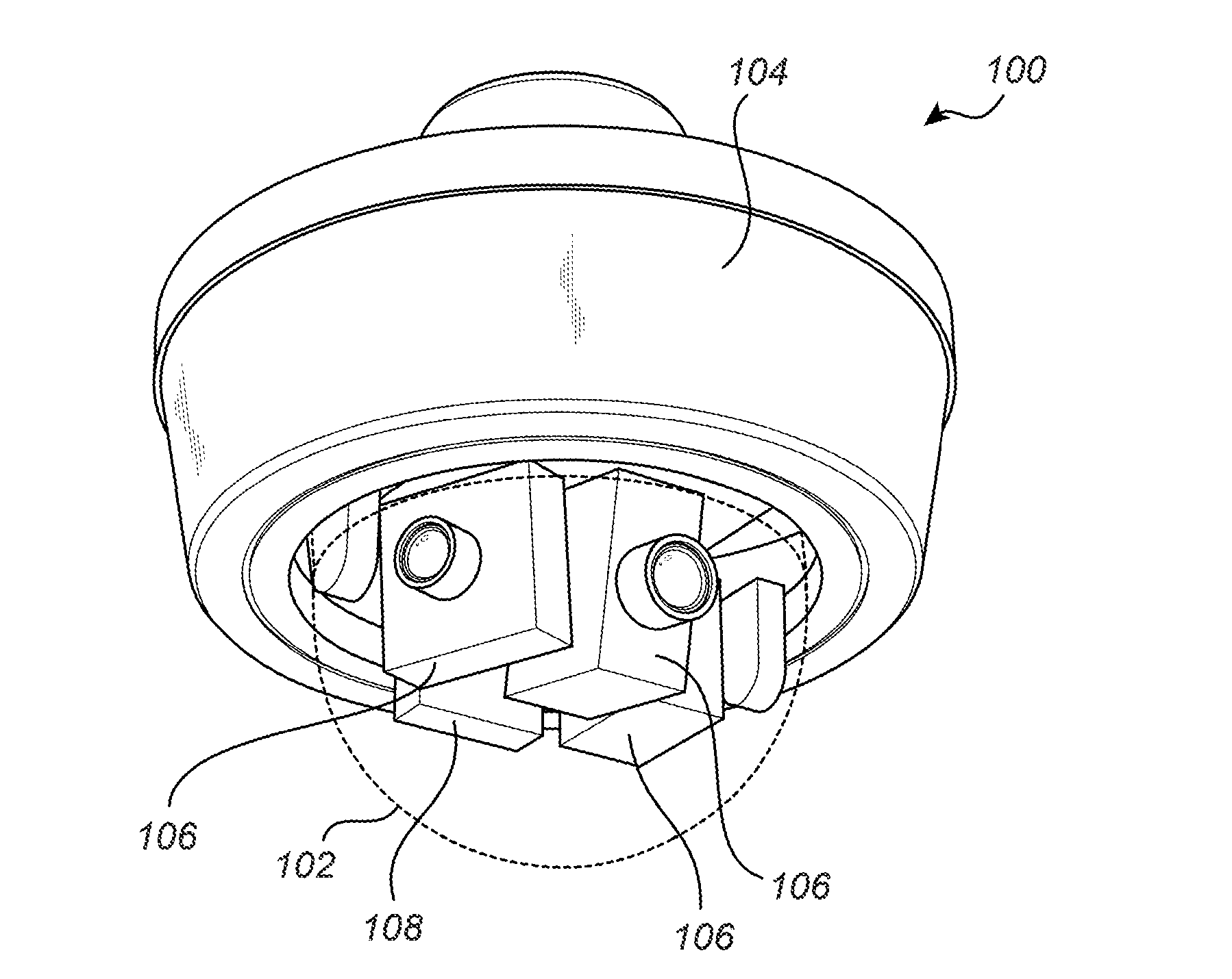
[0049]FIG. 1 shows a monitoring camera device 100 comprising a dome window 102 (indicated with dotted lines), a mounting base 104 and a plurality of camera heads 106.

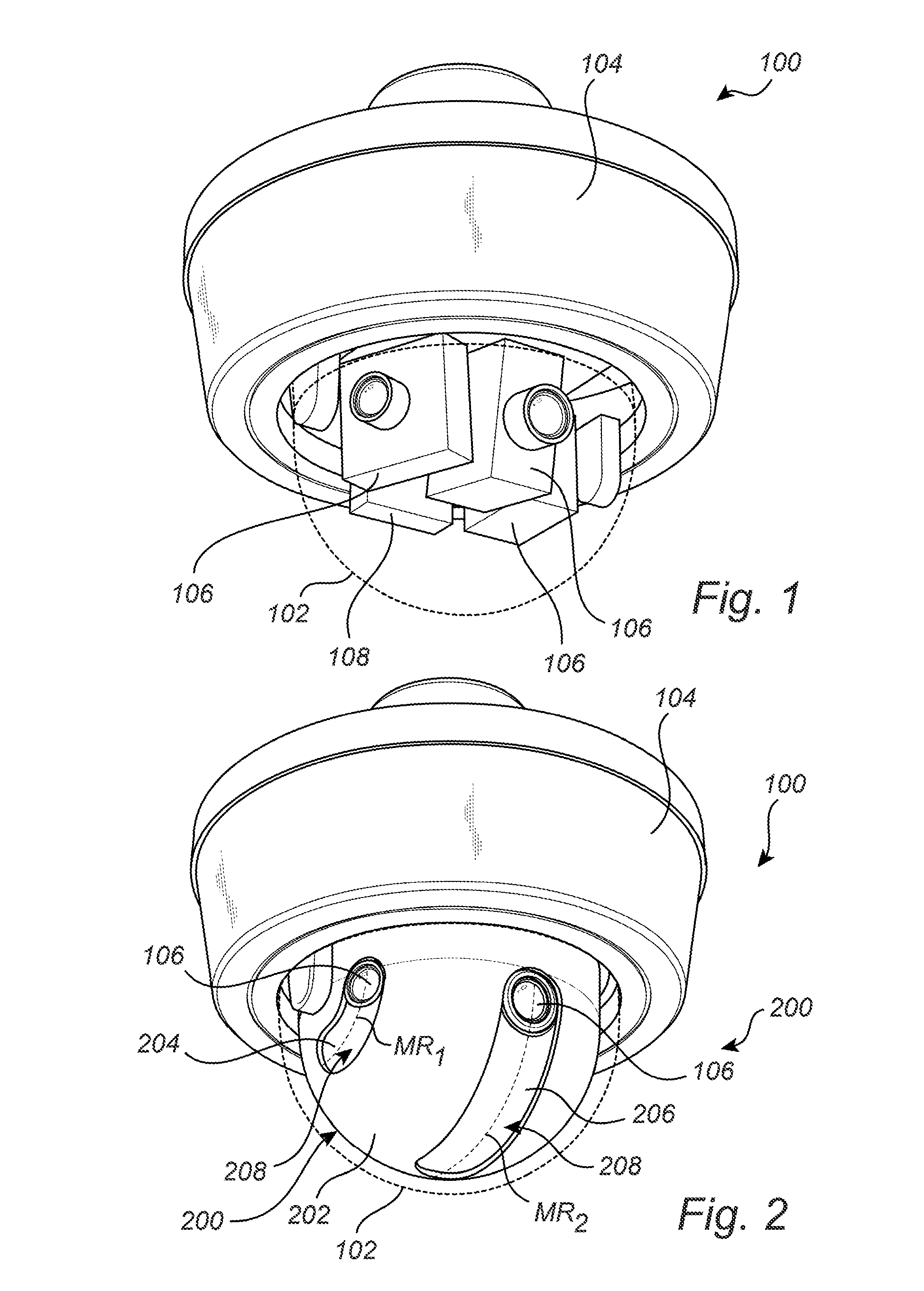
[0050]The monitoring camera device 100 according to the embodiment shown in FIG. 1 is for reasons of clarity depicted without the inventive arrangement comprising an enclosure and a shield. The arrangement will however be described in detail below with reference to FIGS. 2 and 3a-3b.

[0051]According to the embodiment shown in FIG. 1, the monitoring camera de...


PUM


Abstract

An arrangement for a monitoring camera device having a camera head being movable within a movement range (MR1, MR2) is provided. The arrangement comprises an enclosure for covering the interior of the monitoring camera device and having an opening for the camera head providing a free line of sight for an arbitrary camera head position within the movement range (MR1, MR2), a shield movably arranged relative the enclosure for masking parts of the opening not being used for providing the free line of sight for the arbitrary camera head position, the shield comprising a first and a second shield portion mutually movably arranged, wherein the shield is maneuverable between a compressed state and an extended state by movement of the first shield portion relative to the second shield portion. A monitoring camera device comprising the arrangement is further provided.

Description

CROSS REFERENCE TO RELATED APPLICATION[0001]This application claims the benefit of European Patent Application No 14188950.1 filed on Oct. 15, 2014, which is incorporated by reference as if fully set forth.FIELD OF THE INVENTION[0002]The invention relates to an arrangement for a monitoring camera device and a monitoring camera device comprising such an arrangement.BACKGROUND OF THE INVENTION[0003]A monitoring camera device such as a network camera device may be used in many different situations, both indoors and outdoors, to monitor a scene. The monitoring camera device often comprises a camera head where the camera head is movable within a movement range for adjustment during the installation of the monitoring camera device. This simplifies the installation and alignment of the camera head such that a desirable view of the scene is achieved by the monitoring camera device. The camera head may additionally or alternatively be movable within a movement range during operation of the m...

Claims


Application Information

Patent Timeline
IPC IPC(8): H04N5/225H04N5/232
CPCH04N5/23206H04N5/2252G08B13/19619G08B13/1963G08B15/001G03B17/08F16M11/10F16M11/18F16M11/2014F16M13/027H04N23/50H04N23/51
Inventor ELENSI, MIKAELLUNDBERG, MARCUS
Owner AXIS
Why Eureka
Try Eureka