
Digital control method for low output dimming of light emitting diode (LED) drivers

Active Publication Date: 2016-04-21
GE LIGHTING SOLUTIONS LLC
View PDF0 Cites 6 Cited by
  • Summary
  • Abstract
  • Description
  • Claims
  • Application Information

AI Technical Summary

Benefits of technology

The patent describes a method and system for reducing visual fluctuations in light output at low pulse width modulation levels. The method involves measuring the input voltage and calculating a reference voltage based on the input voltage and the power supply voltage. The system includes an LED driver and input / output pins for transferring data signals into and out of a microcontroller. The microcontroller controls the light output of the LED driver through pulse width modulation signals. The system can adjust the light output based on the input voltage and reference voltage to reduce visual fluctuations.

Problems solved by technology

A small change in voltage can cause a large change in current.
If the maximum voltage rating is exceeded by a small amount, the current rating can be exceeded by a large amount, potentially damaging the LED.
However, this methodology of measuring the output and then adjusting the pulse width modulation output (PWM) accordingly can cause problems in the lower levels of PWM output in relation to the light output.
Although very complicated and advanced digital filters have been developed in digital dimming applications, the flickering problem can still persist at a difference between the digital output signal values of 151 and 150.999.
This problem cannot, however, be fixed through adjusting to a rounding methodology, such as floor or ceiling based rounding, which rounds to the nearest integer either up or down.
Therefore, the flickering problem is still prevalent at the digital output signal values between 150 to 150.001.
The drawback of these methods is that the implementation requires too much memory and thus requires a more expensive microchip.
Another disadvantage is that these methods do not account for small average changes of the 0-10V line, which will cause changes of the PWM output.

Method used


Image

  • Digital control method for low output dimming of light emitting diode (LED) drivers
  • Digital control method for low output dimming of light emitting diode (LED) drivers
  • Digital control method for low output dimming of light emitting diode (LED) drivers

Examples


Embodiment Construction

[0023]The following detailed description is merely exemplary in nature and is not intended to limit the applications and uses disclosed herein. Further, there is no intention to be bound by any theory presented in the preceding background or summary or the following detailed description.

[0024]A system and method of controlling flickering at low level voltages with very minimal CPU usage is provided. In at least one aspect, the present invention provides a digital control method for use in applications with LED drivers to remove any visible changes in light output during low current output dimming. In various embodiments, the system and method addresses the existence of visual fluctuations of light output at low PWM levels. In at least one aspect, the device and method compares the percent change of a previously applied input voltage value to the PWM output.

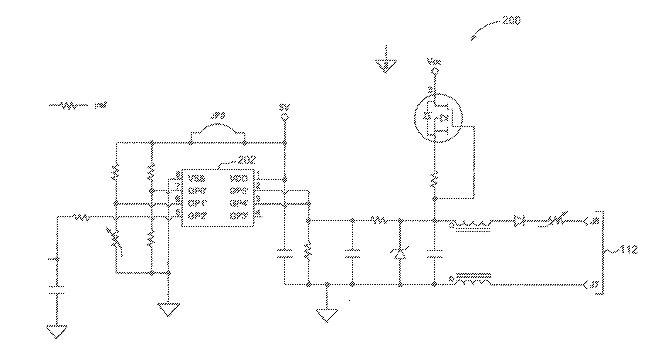
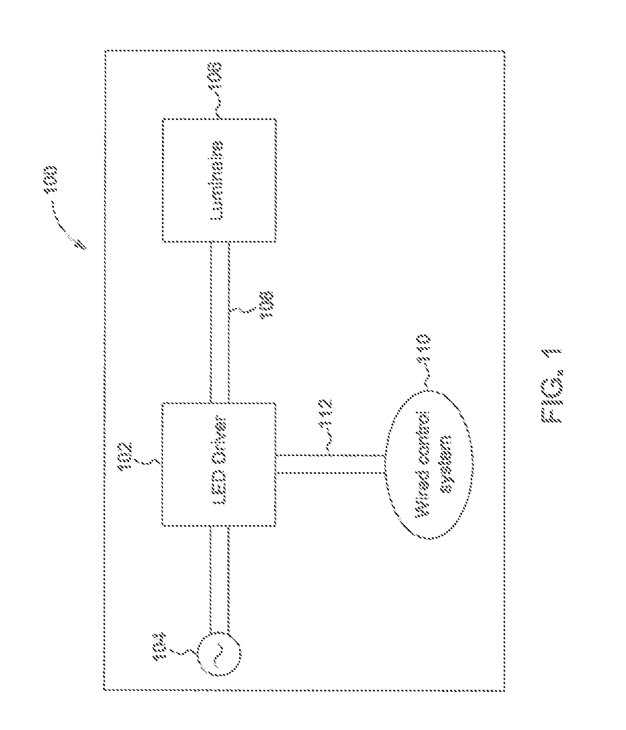
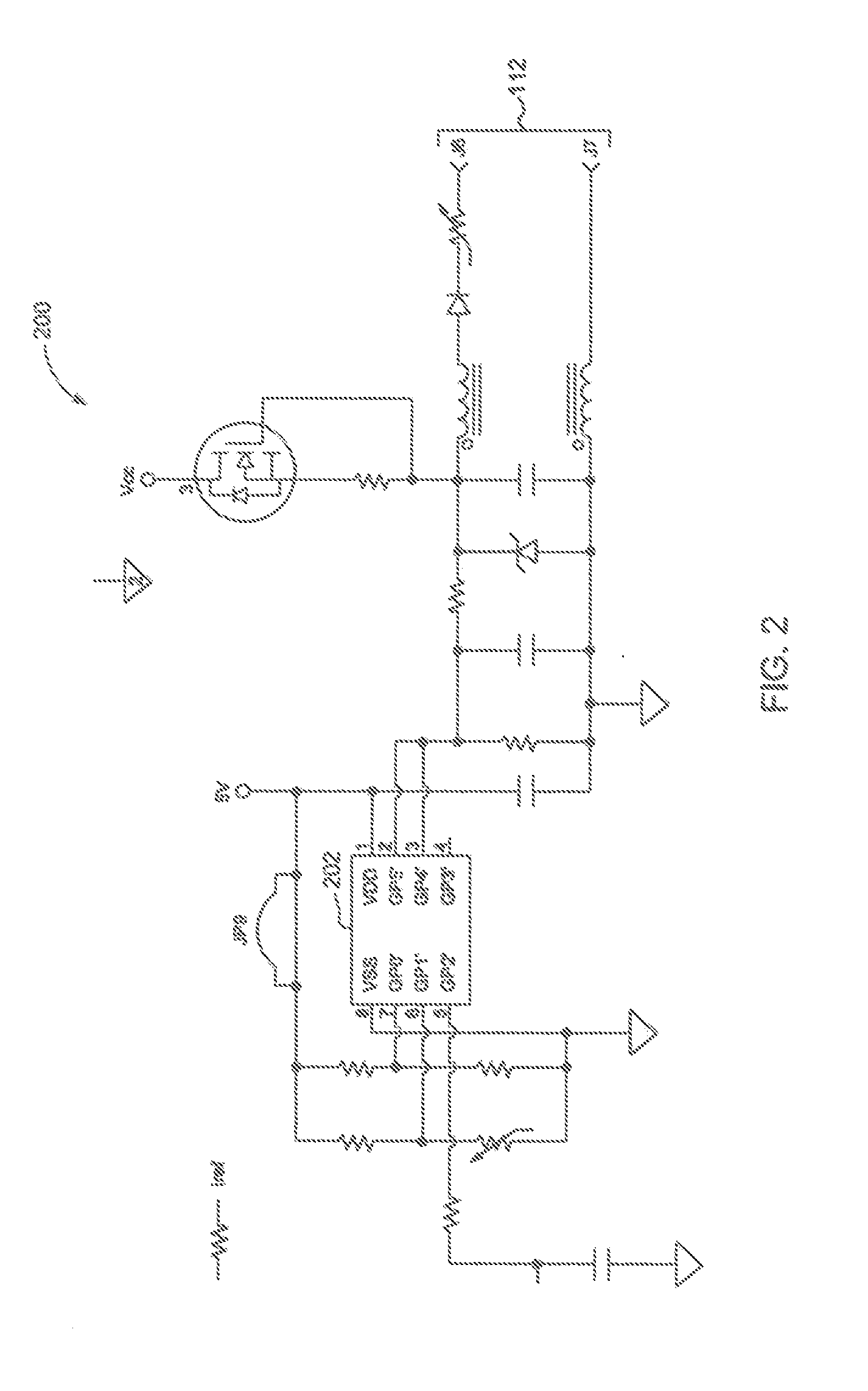
[0025]An exemplary system 100 for a dimming LED driver circuit is illustrated in FIG. 1. In various embodiments, the system 100 ...


PUM


Abstract

A method for mitigating visual fluctuation of light output at low pulse width modulation levels is disclosed. The method comprises at least the step of comparing the percent change of a previously applied input voltage value to the pulse width modulation output.

Description

FIELD OF THE INVENTION[0001]The present invention relates generally to driver circuits for light emitting diode (LED) drivers. More particularly, the present invention relates to dimming driver circuits for LED devices.BACKGROUND OF THE INVENTION[0002]The market for LED lamps has grown exponentially as residential and commercial consumers make the change, from incandescent and halogen bulbs, to LED lighting. The typical reasons are better power efficiency and much longer lifetime. In addition to the benefit of saving energy, consumers also want the same features in LED lamps that are provided for the halogen bulbs; specifically, the ability to dim the light because it provides the desired ambience.[0003]Technically, an LED is generally understood as a semiconductor device that generates light when electrical energy is applied to the device. Multiple LEDs can be formed into an array and powered as a unit.[0004]LEDs are voltage sensitive devices. An LED must be supplied with a voltage...

Claims


Application Information

Patent Timeline
IPC IPC(8): H05B33/08H05B44/00
CPCH05B33/0845H05B45/10
Inventor WHITE, ANTHONY STEVENSCHEIDEGGER, NINA ROSEYAO, GANG
Owner GE LIGHTING SOLUTIONS LLC
Learn More