

Near-field spatial multiplexing
- Summary
- Abstract
- Description
- Claims
- Application Information
AI Technical Summary
Benefits of technology
Problems solved by technology
Method used
Image

Examples
Embodiment Construction
System Overview
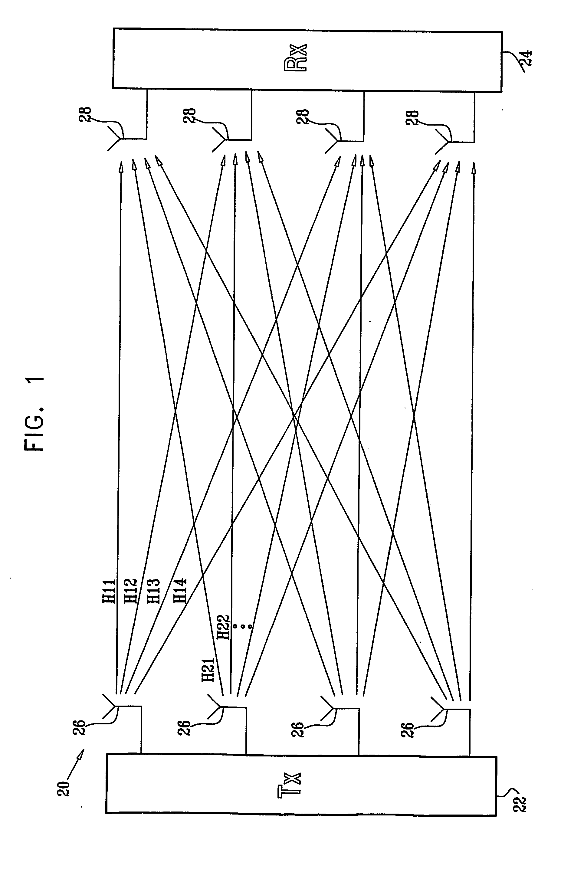
[0037]FIG. 1 is a block diagram that schematically illustrates a wireless data transmission system 20, in accordance with a preferred embodiment of the present invention. System 20 comprises a transmitter 22 and a receiver 24, which are connected by a wireless link formed by multiple transmit antennas 26 and receive antennas 28. Each of the receive antennas receives signals from all the transmit antennas, with amplitude and phase determined by a complex channel transfer function matrix H, having elements H11, H12, . . . , as shown in the figure. In other words, the transmitted signal vector x and the received signal vector y (made up of the individual complex signals xi and yj transmitted and received by the different antennas 26 and 28) are related by the expression:
y=Hx+n (1)
Here n represents the noise received at each antenna. Hij is the complex transfer function from transmit antenna i to receive antenna j, and represents generally both amplitude attenuation and...
PUM
 Abstract
Description
Claims
Application Information