Device for frothing a liquid

a liquid and device technology, applied in beverage vessels, household appliances, kitchen equipment, etc., can solve the problems of clogging the device, difficult cleaning of the piping split, and accumulation of milk residue, and achieve the effect of convenient cleaning and easy disassembly

Active Publication Date: 2016-04-28
VERSUNI HLDG BV
View PDF3 Cites 7 Cited by
  • Summary
  • Abstract
  • Description
  • Claims
  • Application Information

AI Technical Summary

Benefits of technology

[0040]The second frothing unit comprises a first body and a second body, wherein the first body of the second frothing unit comprises a first part of a second mixing unit and a first part of a second frothing chamber, and wherein the second body of the second frothing unit comprises a second part of the second mixing unit and / or a second part of the second frothing chamber, and wherein the first frothing unit and the second frothing unit comprise a common first body and / or a common second body, the common first body comprising the first body of the first frothing unit and the first body of the second frothing unit, the common second body comprising the second body of the first frothing unit and the second body of the second frothing unit. The advantage of this embodiment is easy disassembly and easy cleaning also for multiple frothing units. In the most basic configuration, there are only two body parts, the common first body and the common second body. By separating these two body parts access is provided to all mixing units and all frothing chambers for cleaning purposes. It should be noted that from a user perspective, a ‘body’ is a part that is not separable, even though a body can be manufactured from a plurality of parts, for example if hollow spaces such as a steam pipe need to be provided.
[0041]In another embodiment, the device for frothing a liquid further comprises a rotatable liquid connector for receiving the liquid from different directions, wherein the rotatable liquid connector is connected to the liquid splitter. A container comprising the liquid can be connected to the liquid connector, for example, via a hose or pipe. The advantage of this embodiment is that liquid can be provided from the different directions, for example a milk container can be placed at either side of the device for frothing a liquid.

Problems solved by technology

However, there are problems involved with these approaches.
A disadvantage of a piping split is that cleaning of the piping split is difficult.
Furthermore, milk residue can build up, (partially) clog the device and impair the quality of the milk froth.
A disadvantage of a gutter split is that it does not allow for a compact design.
As a further disadvantage the splitting accuracy is limited and is at least influenced by an accidental non-horizontal placement of the appliance.
It is thus difficult to provide two streams that provide equal amounts of froth.

Method used


Image

  • Device for frothing a liquid
  • Device for frothing a liquid
  • Device for frothing a liquid

Examples


first embodiment

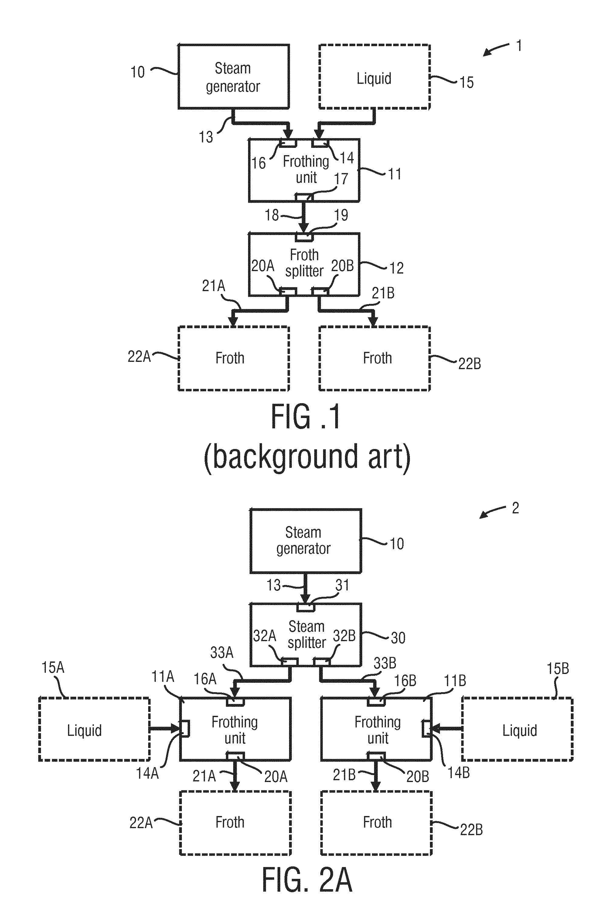
[0060]FIG. 2A shows a device 2 for frothing a liquid 15A, 15B according to an aspect of the present invention. The device 2 comprises a steam generator 10, a steam splitter 30 as well as a first frothing unit 11A and a second frothing unit 11B. The steam generator 10 generates a stream of steam 13. The steam splitter 30 comprises a steam-splitter inlet 31, a first steam outlet 32A and a second steam outlet 32B. The steam splitter 30 receives the stream of steam 13 at the steam-splitter inlet 31 and splits the stream of steam 13 into a first sub-stream of steam 33A and a second sub-stream of steam 33B. The first sub-stream of steam 33A is provided at the first steam outlet 32A and the second sub-stream of steam 33B is provided at the second steam outlet 32B.

[0061]The first frothing unit 11A comprises a first liquid inlet 14A for receiving the liquid 15A, a first steam inlet 16A for receiving the first sub-stream of steam 33A, and a first froth outlet 20A for providing a first stream ...

second embodiment

[0064]FIG. 2B shows a device 3 for frothing a liquid 15 according to an aspect of the present invention. Differences with respect to the embodiment shown in FIG. 2A are highlighted instead of repeating corresponding features. The embodiment shown in FIG. 2B further comprises a steam-splitter control 34, a liquid splitter 40 and a liquid-splitter control 44.

[0065]The liquid splitter 40 comprises a liquid-splitter inlet 41, a first liquid outlet 42A and a second liquid outlet 42B. The liquid splitter 40 receives the liquid 15 at the liquid-splitter inlet 41 and splits the liquid 15 into a first sub-stream of liquid 43A and a second sub-stream of liquid 43B. The first sub-stream of liquid 43A is provided at the first liquid outlet 42A and the second sub-stream of liquid 43B is provided at the second liquid outlet 42B. The first liquid outlet 42A of the liquid splitter 40 is connected to the liquid inlet 14A of the first frothing unit 11A. The second liquid outlet 42B of the liquid spli...


PUM


Abstract

A device (2, 3, 4, 5, 6, 7, 8) for frothing a liquid (15) is presented, in particular for providing two or more streams of froth in parallel. The device comprises: a steam generator (10) for generating a stream of steam (13), a steam splitter (30) for splitting the stream of steam (13) into a first sub-stream of steam (33A) and a second sub-stream of steam (33B), wherein the first sub-stream of steam (33A) is provided at a first steam outlet (32A) and the second sub-stream of steam (33B) is provided at a second steam outlet (32B), a first frothing unit (11A) having a first liquid inlet (14A) and a first steam inlet (16A), a second frothing unit (11B) having a second liquid inlet (14B) and a second steam inlet (16B), wherein the first steam outlet (32A) of the steam splitter (30) is connected to the first steam inlet (16A) of the first frothing unit (11A) and the second steam outlet (32B) of the steam splitter (30) is connected to the second steam inlet (16B) of the second frothing unit (11B). In a further aspect a coffee machine (50) comprising a coffee brewing unit (51) and the device for frothing a liquid is presented.

Description

FIELD OF THE INVENTION[0001]The present invention relates to a device for frothing a liquid, in particular for providing two or more streams of froth in parallel. Furthermore, the present invention relates to a coffee machine including the device for frothing a liquid.BACKGROUND OF THE INVENTION[0002]Many automated coffee machines in the cup-by-cup segment have the ability to prepare two cups of coffee simultaneously. Some automated coffee machines are able to produce milk froth as well in order to serve milk-based coffee drinks[0003]Frothing a liquid involves applying a gas like air to the liquid and mixing the liquid with the gas for obtaining bubbles in the liquid. The result is referred to as foam or froth. In many cases, the liquid to be frothed is milk. Especially in the field of making coffee and coffee specialties, there is a need for a device which is capable of frothing milk in a user-friendly manner. It is a well-known option to combine a frothing process of milk with a h...

Claims


Application Information

Patent Timeline
Patent Type & Authority Applications(United States)
IPC IPC(8): A47J31/44
CPCA47J31/4489A47J31/4485A47J31/44
Inventor NOORDHUIS, JOEKEBEEKMAN, JARNOHOLTEN, HENDRIKUS LODEWIJK JOSEPH FRANCISCUSOGINK, JUDITH MARGREET HANNEKEFEIJEN, FRANSISCUS HERMANNUS
Owner VERSUNI HLDG BV
Why Eureka
Try Eureka